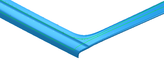
Use the Profile finishing page to pick a selection of surfaces and profile around the outside of these surfaces.
All the examples shown here have an invisible base plane underneath the model. If no base plane is present, the toolpath will be different and in some cases no toolpath will be created.
Drive curve determines which curve or set of curves is used to create the cutting moves.
Side —Select the edge of the surface to profile.
Side — Inside edge
Side — Outside edge

Radial offset — Enter the gap between the tool and the edge curve of the surface.

 —
Radial offset of
0
—
Radial offset of
0
 —-
Radial offset of
5
—-
Radial offset of
5
Base position — Select how to determine the lowest position of the profiling pass.

selected surface
Automatic — Drops the tool onto the part.

If the tool misses the part then no toolpath is produced. In this case if there is no base plane then half of the toolpath "disappears".

Drive curve — Uses the edge of the selected surface.
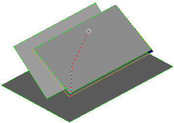
Axial offset — Enter the depth of the toolpath relative to the selected surfaces. So, if you want the toolpath to be above the selected surfaces enter a positive value. Zero depth is where the tool touches the surfaces. This option is available only if you select a Lower limit of Drive curve. The following toolpath is created if you select the two squares and have a base plane.
Selecting a base plane produces:

—
Axial offset of
0
—
Axial offset of
20
Surface joining tolerance — Enter a value to disassociate the machining tolerance from the tolerance used to define what is a gap between surfaces. If the gap between surfaces is larger than the machining tolerance, PowerMill creates two toolpath segments. To ensure one continuous toolpath across a gap, use a larger Surface joining tolerance.
Gouge check — Select this option so PowerMill checks the toolpath to see if any part of it gouges or deselect to turn gouge checking off.
Degouge tolerance — Enter the maximum distance, normal to the surface, that the toolpath can move to find a safe position. If gouges greater than this value are detected, then the tool is lifted axially to avoid the gouge.
Tolerance — Enter a value to determine how accurately the toolpath follows the contours of the model.
Cut direction — Select the milling technology.
Select a Cut Direction from the following:
-
Climb — Select to create toolpaths using only climb milling, where possible. The tool is on the left of the machined edge when viewed in the direction of tool travel.

-
Conventional — Select to create toolpaths using only conventional or upcut milling, where possible. The tool is on the right of the machined edge when viewed in the direction of tool travel.

- Any — Select to create toolpaths using both conventional and climb milling. This minimises the tool lifts and tool travel.
Thickness — Enter the amount of material to be left on the part. Click the
Thickness
 button to separate the
Thickness
box in to
Radial thickness
button to separate the
Thickness
box in to
Radial thickness
 Axial thickness
 . Use these to specify separate
Radial and
Axial thickness as independent values. Separate
Radial and
Axial thickness values are useful for orthogonal parts. You can use independent thickness on sloping walled parts, although it is more difficult to predict the results.
. Use these to specify separate
Radial and
Axial thickness as independent values. Separate
Radial and
Axial thickness values are useful for orthogonal parts. You can use independent thickness on sloping walled parts, although it is more difficult to predict the results.
Radial thickness — Enter the radial offset to the tool. When 2.5-axis or 3-axis machining, a positive value leaves material on vertical walls.

Axial thickness — Enter the offset to the tool, in the tool axis direction only. When 2.5-axis or 3-axis machining, a positive value leaves material on horizontal faces.

 Component thickness — Click to display the
Component thickness
dialog, which enables you to specify the thicknesses of the different surfaces.
Component thickness — Click to display the
Component thickness
dialog, which enables you to specify the thicknesses of the different surfaces.
 Set stepdown from tool — Click to automatically define the stepdown from the tool geometry.