This example uses the 5_axis_Test_top.dgk model in the Examples folder.
- Select the surface.
- From the
Boundaries context menu, select
Create Boundary > Contact Point.
This displays the Contact Point Boundary dialog.
- Click the
Model
 button to create the contact point boundary for the selected surfaces.

This boundary is independent of the tool. The tool-specific boundary is calculated automatically on toolpath creation.
- Click Accept to close the dialog.
- Create a block at the limits of the model, and a 20 mm ball nosed.
- Create a
Raster Finishing toolpath using the
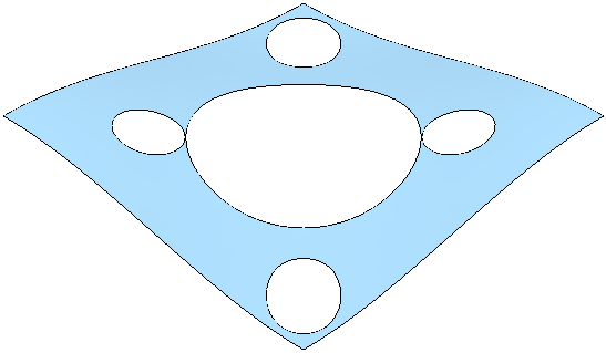
Contact Point Boundary. The
Contact Point Boundary
is converted to the actual boundary required for the 20 mm ball nosed tool:

If you used a Selected Surface Boundary you would see the following result:

In this case the toolpath can roll-over the edges, whereas with the Contact Point Boundary the roll-over is prevented.
Contact Point boundaries work well if you select several surfaces or surfaces with two coincident sides (such as a cylinder).
- Select the cavity of the
5_axis_Test.dgk model.

- Create a
Contact Point
boundary from this (following steps 2-4 above), the desired boundary is created.
