This example shows how to construct a workplane from the current machine tool position. The workplane is aligned with the tool axis and head position.
This can be useful if you need to insert a workplane between two multi-axis toolpaths in an NC program for access purposes (a 5-axis link move). If you pause the machine tool simulation after the first toolpath and jog the machine to the correct orientation to enable access for the tool, you can then create the workplane.
- Create an NC program that contains more than one toolpath.
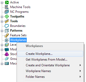
- You know that between the first and second toolpath you will need a 5-axis link move. However, you don’t know the exact orientation of this workplane, so create a new workplane by selecting
Create Workplane from the
Workplanes context menu:

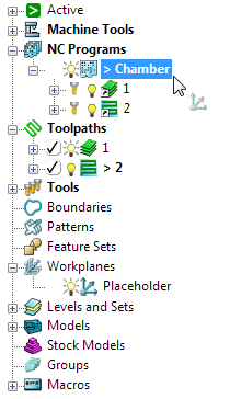
- On the Workplane Editor tab > Workplane panel enter a Name, for example, Placeholder and click Workplane Editor > Finish panel > Accept to create it.
- Drag the workplane between the two toolpaths in the NC program:

- Click Machine Tool tab > File panel > Import to load the machine tool.
- Ensure that the first toolpath is active.
- From the individual toolpath context menu, select Simulate from Start.
- Move the machine tool to the end of the first toolpath, using Simulation tab > Simulation Controls > Step Forward (or using the simulation keyboard shortcuts).
- Click Simulation tab > Position dialog > Machine Tool to display the Machine Tool Position dialog.
- Use the axis sliders on the
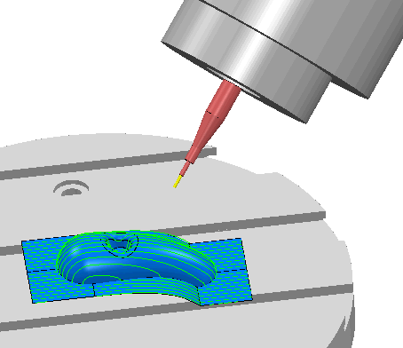
Machine Tool Position dialog to jog the machine to the desired position for the link move.

- From the individual Workplane context menu, select Workplane Editor.
- Click Workplane Editor tab > Align panel > Align > To Tool and Reposition.
- Click Workplane Editor tab > Finish panel > Accept.
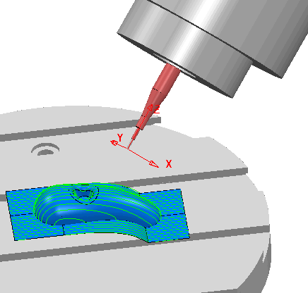
The Placeholder workplane is now in the required orientation:

- Close the Machine Tool Position dialog.
Note: This technique enables you to construct a toolpath corresponding to a given machine orientation rather than trying to work out the machine orientation for a given toolpath.
Note: This technique can also be used to; define the orientation of the machine tool for 3+2-axis machining, and define the limits for a multi-axis machine tool, by moving the machine tool to its travel limits, creating a workplane, and selecting
Align to Tool. Then, from the
Properties available on the individual workplane context menu, you can display the
Elevation
and
Azimuth
angles. These angles are the same as those needed in the
Limits
tab on the
Tool Axis Direction dialog.
Note: This also works for standard animation without loading a machine tool.