Create a probe path to measure specified points on a surface.
- Click Toolpath tab > Create panel > Toolpath.
- On the Strategy Selector dialog, choose the Probing category, then click Surface Inspection.
- Click OK.
- In the Distances area of the Surface inspection page specify the:
- Approach Distance
 .
.
- Search Distance
 .
.
- Retract Distance
 .
.
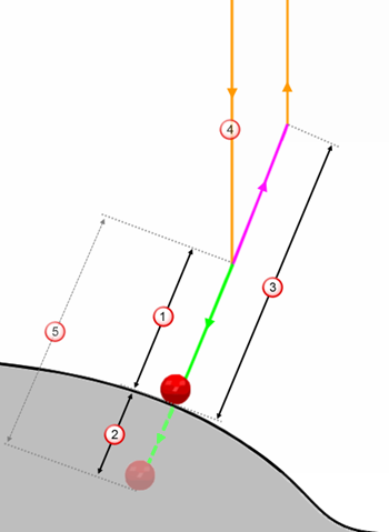 Approach Distance — The height above the surface normal, where the probe starts approaching the surface at the
Measure feed rate.
Search Distance — The distance up to which the probe continues searching for material, when no contact is made with the part over the
Approach Distance. If no contact is made along the
Search Distance, the probe returns an invalid measurement.
Retract Distance — The height above the surface normal, up to which the probe retracts away from the surface at the
Connection feed rate.
Approach Distance — The height above the surface normal, where the probe starts approaching the surface at the
Measure feed rate.
Search Distance — The distance up to which the probe continues searching for material, when no contact is made with the part over the
Approach Distance. If no contact is made along the
Search Distance, the probe returns an invalid measurement.
Retract Distance — The height above the surface normal, up to which the probe retracts away from the surface at the
Connection feed rate.
 Approach move — The path of the probe tool as it moves down from the safe area, to the
Approach Distance. The speed of this move is specified by the
Approach feed rate.
Approach move — The path of the probe tool as it moves down from the safe area, to the
Approach Distance. The speed of this move is specified by the
Approach feed rate.
 Measure move — The path of the probe tool as it searches for the part along the
Approach Distance, up to the
Search Distance. The speed of this move is specified by the
Measure feed rate.
Measure move — The path of the probe tool as it searches for the part along the
Approach Distance, up to the
Search Distance. The speed of this move is specified by the
Measure feed rate.
- Approach Distance
- In the Tolerances area, specify the Upper Tolerance and Lower Tolerance.
These are the maximum distances, above and below the nominal surface, up to which probed points are in-tolerance.
- Enter a Surface Offset to compensate for the thickness of a part. This offsets the surface nominals by the specified distance.
- In the Points area, choose the Pattern used to specify the surface probe points. If you do not have a pattern, use the options in this area to create a pattern and its geometry.
- Click Calculate.