This example looks at tool axis interpolation and point redistribution within a selected region. The machine tool movement at the start of each toolpath segment is smoothed by making the tool axis change more gradual.
This example uses the impeller.dgk model in the Examples folder, and assumes that you have completed the tool axis editing example.
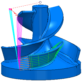
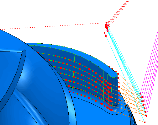
- Look at the fillet of the blade toolpath, and click Toolpath tab > Draw panel > Display > Points.
- Click Toolpath Edit tab > Edit panel > Edit Within Region to display the Edit Toolpath Within Region dialog.
- On the Select Regions tab, select Polygon in the Define Region By list, and select Inner in the Side list.
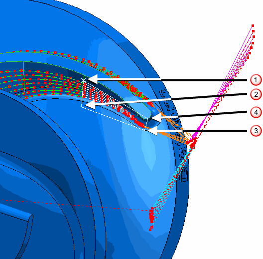
- Create a polygon by selecting points similar to points
 ,
,
 ,
,
 , and
, and
 below:
- Click
Save Selection. The selected portions of the toolpath turn white.
If you want to add additional portions of toolpath, select them first, and then click the Save Selection button to add them to the current selection. In this case, you have already selected the required portion.
- Select the Specify Changes tab and from the Type of Editing list, select Axis Interpolation.
- Click the
Point distribution
 button. In the
Point Distribution dialog which appears:
button. In the
Point Distribution dialog which appears:
- In the Output type list, select Redistribute.
- In the Tolerance factor box, enter 0.5.
- Select the Point separation distance option.
- In the Maximum distance box, enter 0.5.
- In the Mesh factor box, enter 0.1.
- Select the Limit maximum triangle length option.
- In the Maximum triangle length box, enter 1.0.
- Click Accept to close the Point distribution dialog.
- On the
Edit Toolpath Within Region dialog, click
Apply to create the additional points.