This example looks at the different options available for tool axis editing using the Impeller.dgk model in the Examples folder.

Before you can edit the toolpath you must create one. This example uses a surface machining toolpath, which is then trimmed so that the near-vertical end fillet of the blade remains unmachined.
- Calculate a Block and create a 10 mm Ball Nosed tool.
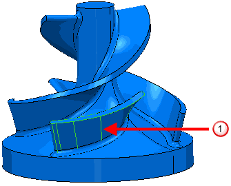
- Select the splitter blade
 .
.
- Click Home tab > Create Toolpaths panel > Toolpaths to display the Strategy Selector dialog.
- From the Finishing category select Surface Finishing.
- On the Surface Finishing > Pattern page select a Start corner of Max U max V.
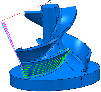
- On the Tool Axis page
- Select a Tool Axis of Lead/Lean.
- Enter a Lean of -70.
- Click Calculate.
- Click Close.
- To limit the toolpath so the end fillet is not machined: From the individual Toolpath context menu, select Edit > Limit.
- In the Toolpath Limit dialog:
- Select a Limit to of Polygon.
- Select Delete Original.
- Select a Save of Outer.
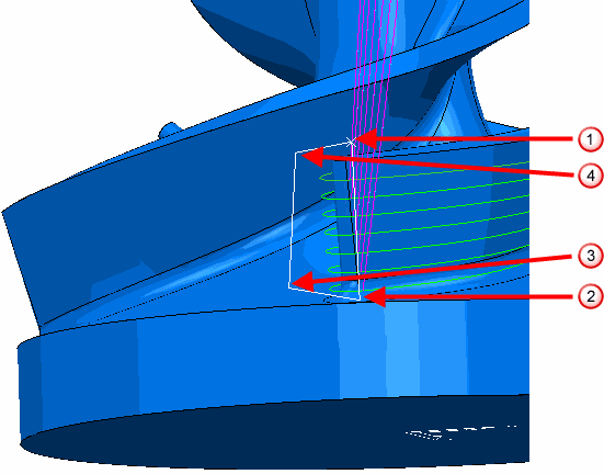
- Create a polygon by selecting points similar to points ,
 ,
,  , and
, and  below:
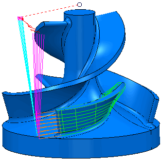
- Click Apply, then click Cancel to trim the toolpath and close the Toolpath Limit dialog.
- Click Home tab > Setup panel > Toolpath Connections to display the Toolpath connections dialog.
- Select the Lead ins tab.
- Select a 1st Choice of Extended Move.
- Enter a Length of 30.
- Click
 to copy the Extended Move to the Lead Outs tab.
 - Click Apply, then click Accept.
These examples look at editing this toolpath in a variety of ways:
- The Point Distribution example looks at tool axis interpolation to smooth the machine tool movement in a specified region of the toolpath.
- The Tool Axis editing example shows how to modify the toolpath tool axis locally to gain extra clearance.
- The Multiple Selection example shows how to multi-select regions of a toolpath before editing the tool axis.
- The Blend Distance example shows how to smooth the transition between the original and the edited tool axis.