When creating a toolpath, PowerMill machines inside the selected boundary segment. If no segments are selected, PowerMill uses the whole boundary, which can minimise the amount of boundaries required for editing. However, you need to take care because PowerMill does not record which part of the boundary was selected when the toolpath was created, and so it is more difficult to recreate the toolpath.
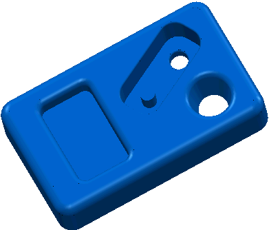
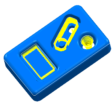
This example uses the Pockets.tri model in the Examples folder.
- Create a Block.
- Create a Tool.
- Create a
Shallow Boundary.
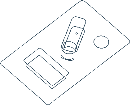
- Create a
3D Offset toolpath on the shallow areas:
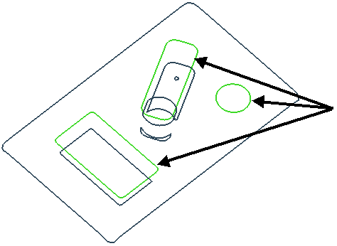
- Select the three boundary segments at the top of each pocket:
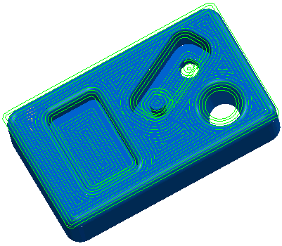
- Create a
Constant Z toolpath.
Note: You can see that the constant Z toolpath has only been created inside the selected segments of the boundary.