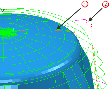
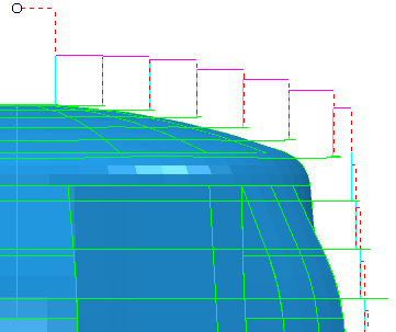
The Links page specifies how to make the link moves between the cutting moves in a toolpath.
Links are specified as a first choice link, second choice link, and a default link. You can apply constraints to the links to define the circumstances in which they are used. If the constraint criteria of the first choice link are not satisfied, or if they are satisfied but could not be applied, for example, it is unsafe, PowerMill tries to apply the second choice link. If the constraint criteria of the second choice link are not satisfied PowerMill applies the default link.
You can choose to create links with no constraints. In this instance PowerMill applies the type of link chosen where appropriate if possible. If Gouge check is selected the 1st choice and 2nd choice links are only created if they are safe, otherwise the Default link is used.
If you choose to create links with no constraints and Gouge check is not selected, then the 1st choice link will be used in all cases, regardless of safety.
Use the following options to specify your link properties:
1st choice — Select the type of link moves to connect consecutive cutting passes for your first choice. PowerMill applies this link where its constraint criteria are met.
2nd choice — Select the type of link moves to connect consecutive cutting passes for your second choice. PowerMill applies this link where its constraint criteria are met.
Default — Select the type of link moves from the list to be used if the constraint criteria for both the 1st choice and 2nd choice links are not met, or if they gouge.
 Short link of
Straight
Short link of
Straight
 Default
link of
Skim
Default
link of
Skim
The Default link options are:
-
Safe
— The tool moves to the safe area before making the link move.

-
Incremental
— The tool descends at rapid feed from the safe area to the specified incremental distance above the target point, and then plunges the remaining distance. If you have a multi-axis toolpath, the tool retracts a set distance along the tool axis and then retracts to the safe area. It comes down from the safe area and completes the approach along the tool axis. The distance moved along the tool axis is controlled by the
Incremental plunge distance on the
Moves and clearances
tab of the
Toolpath connections
dialog.

-
Skim
— The links traverse clear of the part by the specified incremental distance, descend at rapid feed to the specified incremental distance above the contact point, and then plunge the remaining distance.
- Simultaneous — The tool axis is free to move along the link.
-
Move then rotate — The behaviour is dependent on the path:
- Rapid surface paths — The tool moves to the position above its target within the rapid surface, then changes the tool axis when it leaves the rapid surface.
- Direct paths — The tool axis is fixed until it reaches the end of the link.
-
Rotate then move — The behaviour is dependent on the path:
- Rapid surface paths — The tool axis changes when the tool reaches the rapid surface, it then moves into the next position.
- Direct paths — The tool axis changes at the start of the link.
- Rapid surface normal — The tool axis is fixed perpendicular to the rapid surface as it moves across it. This option is only available for toolpaths that travel through the rapid surface.
- Reset machine tool — The tool axis is aligned to the machine tool's initial orientation across the course of the link.
- Rotation point — The tool axis is fixed as it moves through the safe area to the origin of the specified workplane. The tool axis then rotates and moves to the next link.
Apply constraints — Select this option to apply constraints to your links and then select a constraint from the list. Selecting a constraint from the list creates an additional field to apply further constraints. 1st choice and 2nd choice links have a maximum of 2 constraints when using the strategy dialog. If more than one constraint is selected they must all be satisfied for a link to be applied.
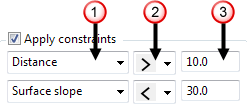 Select a constraint type from the list:
- Distance — Constrain the link by its distance spanned.
- Surface slope — Constrain the link by the slope angle of the surface at either end of the link.
- Angular change — Constrain the link by the angular change of the tool axis.
- Azimuth — Constrain the link by the change in the azimuth angle of the tool axis.
- Elevation — Constrain the link by the change in the elevation angle of the tool axis.
Select an option from the list to define the constraint limit:
-
 — The constraint is satisfied if the parameter is less than the specified value.
-
 — The constraint is satisfied if the parameter is greater than the specified value.
 Enter the constraint value.
Gouge check — Select this option for PowerMill to gouge-check all leads and links.