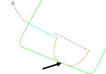
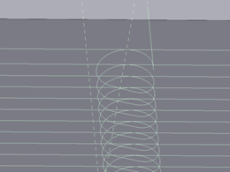
Leads and links displays a summary of the leads and links used to calculate the toolpath.
Use the options on this page to specify general leads and links properties:
Overlap distance — Enter the distance by which a Lead in and Lead out can overlap a closed toolpath segment.

Allow start points to be moved — When selected, this option moves the start points on closed toolpath segments to try and find a non-gouging position. When deselected, PowerMill will not move the start points - this means that if you carefully position a start point, you can prevent PowerMill from moving it.
Stagger start points — When selected, this option moves the start points on successive closed toolpath segments so that the start points are spread out on each segment. This allows the tool to maintain forward motion as it moves from one segment to the next.
- Deselected — The start points for each segment are nearby, causing the tool to reverse in motion when moving from one segment to the next.

- Selected — The start points for each segment are spread out to help the tool maintain forward motion.

Add leads at tool axis discontinuities — When selected, inserts leads and links between continuous segments where there is an angular change in tool axis between neighbouring segments. This ensures that any reorientation of the tool axis at a specific point takes place away from the part.
Angular threshold — Enter the minimum angle required before leads and links are inserted. The angle is the change in the tool axis between neighbouring segments.
Gouge check — Select this option for PowerMill to gouge-check all leads and links.
Selecting Lead in , Lead out, First and last leads, Lead extensions, Links, or Point distribution in the strategy tree also enables you to edit the leads and links.