The cutting moves of the toolpath created in Create the Blisk area clearance toolpath are correct, but the links have to be defined. One of possible solutions is:
- Click Home tab > Setup panel > Toolpath Connections to display the Toolpath connections dialog and click the Lead ins tab.
- In the 1st Choice list select Extended Move.
- Enter a Length of 10.
- Click Copy to Lead Out
 to copy these values to the Lead Outs tab.
- Click the Links tab.
- Select a 1st choice of Circular arc.
- Click Apply constraints.
- Select Distance from the first drop-down list.
- Select
 from the second drop-down list.
 - Enter 250 to be the maximum link distance.
- Select a 2nd choice of Skim.
- Click the Moves and clearances tab.
- Select an Along of Tool Axis.
- Select Automatically Extend.
- Enter a Maximum length of 250.
- Click Apply to apply the changes to the active toolpath.
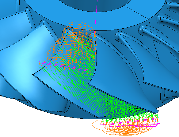
Note: When the Allow Start Points to be Moved on the Lead Ins tab of the Toolpath connections dialog is selected, then the lead in and lead out moves of closed toolpath segments are placed in the middle of the concave part of the main blade. This can leave witness marks on the part. If you deselect this option, the closed toolpath segments start and end at the Z minimum of each blade.