Use the High speed page to control various smoothing options to avoid sharp changes in tool direction when high-speed machining. The available options are dependent on the selected strategy:
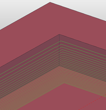
Profile smoothing — Select to enable the arc fitting of profiles to avoid sharp changes in direction for external corners. The arc radius is defined as a proportion of the tool diameter and is calculated using the tool diameter and a multiplication factor. Use the slider to specify the multiplication factor. For example, if you have a tool diameter of 10 mm and a multiplication factor of 0.05, the arc radius is 0.5 mm.
-
Profile Smoothing deselected:

 — The external corners are not smoothed.
 — The internal corners are smoothed.
Using a Radius of 0.2 gives:
 — The external corners are now smoothed.
Note: Arc fitting is important when high-speed machining, as it eliminates sudden changes in tool direction.Note: For vortex machining small trochoids are inadvisable, if possible keep the trochoid radius larger than 1 mm.
— The external corners are now smoothed.
Note: Arc fitting is important when high-speed machining, as it eliminates sudden changes in tool direction.Note: For vortex machining small trochoids are inadvisable, if possible keep the trochoid radius larger than 1 mm.
Raceline smoothing — Select to replace the standard offset with one that can achieve higher feed rates by preventing abrupt changes in force on a machine tool, that are caused by sharp turns in a toolpath. This offset replaces sharp corners with rounded corners and changes the stepover from a fixed to a variable distance. Use the slider to specify the maximum deviation from the specified stepover as a percentage.

— rounded corners
— variable stepover
Trochoidal moves — When selected, this enables trochoidal moves with restrict tool overload settings applied by default.
-
Maximum overload — Use the slider to set the tool overload value required to insert a trochoidal.
Note: When creating a Model Area Clearance toolpath, the Trochoidal moves option is only available when using Offset model or Offset All area clearance style.Note: This option is available only if you select an offset style on the main page of the area clearance strategy.
Links — Select an option to specify how PowerMill creates link moves between offsets within the toolpath.
-
Straight:

-
Smooth:

-
None:

This option is available only if you select an offset style on the main page of the strategy.
-
Fillet corners deselected:
-
Fillet corners selected:

Arc fit corners (2D) — Select to create arcs in all internal corners of a toolpath. This is important when high-speed machining as it eliminates sudden changes in tool direction. The arc radius is defined as a proportion of the tool diameter and is calculated using the tool diameter and a multiplication factor. Use the slider to specify the multiplication factor. For example, if you have a tool diameter of 10 mm and a multiplication factor of 0.05, the arc radius is 0.5 mm.
-
Arc fit corners deselected:
-
Arc fit corners selected:
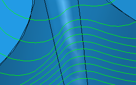
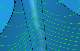
Vertical smoothing — Improves the smoothness of the profiling normal to the surface
-
Up/Down axis (tool diameter units) — Enter the vertical smoothing distance in tool diameter units. This type of smoothing can be effective in removing excessive "judder" caused by offsetting internal corners. It is best to try smoothing with the default values initially. Too much smoothing can distort the profile by flattening out too far.


-
Angular — Enter the smoothing angle. This type of smoothing can be effective when multi-axis machining and can be used to smooth profiles from trimmed surfaces. Trimmed surfaces can have a "lumpy" edge which is then magnified by the profiling. Angular smoothing minimises this. 5
 is the default value.
Axis calculation tolerance — Enter a tolerance value for calculating the tool axis. For a relatively rare number of geometries, the tool axis can waver slightly as it positions accurately on the surfaces. This can be due to small but significant changes in the geometry as the tool moves from one position to another. This tolerance can be larger than the machining tolerance to stabilise the tool axis as it moves across this geometrically varying region. As a consequence excess material may be left on the surface but the load on the tool may be reduced.
For more information on the effects of smoothing, see Tool loading.