Use the Port page of the port area clearance dialog to specify the options for rapid removal of material inside a port.
Pattern — Select a pattern to specify the location of the port and the orientation of the subsequent machining. The pattern serves three purposes:
- Indicates the port to machine.
- Controls the orientation of the slices. The slices are normal to the pattern. If you use Workplane Limits then the workplanes override the pattern.
- Determines which end of the port is machined first.
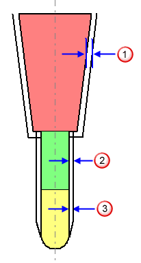
Tool clearance — Enter the tool shank and holder clearance. This is in addition to any Thickness defined and is added to the side of the tool to avoid collision with cusps or unmachined material. Port area clearance uses a series of 3+2 axis slices where ever possible.

 Holder clearance
 Shank clearance
 Tool shaft clearance
Cut direction — Select the milling technology.
Select a Cut Direction from the following:
-
Climb — Select to create toolpaths using only climb milling, where possible. The tool is on the left of the machined edge when viewed in the direction of tool travel.

-
Conventional — Select to create toolpaths using only conventional or upcut milling, where possible. The tool is on the right of the machined edge when viewed in the direction of tool travel.

- Any — Select to create toolpaths using both conventional and climb milling. This minimises the tool lifts and tool travel.
Tolerance — Enter a value to determine how accurately the toolpath follows the contours of the model.
Thickness — Enter the amount of material to be left on the model, within tolerance, when gouge checking.
 Component thickness — Click to display the
Component thickness
dialog, which enables you to specify the thicknesses of the different surfaces.
Stepover  — Enter the distance between successive machining passes towards the centre of the port. Subsequent offsets in a Port Area Clearance toolpath move from the edge of the port towards the centre of the port.

 Copy stepover from tool — Click to load the radial depth of cut from the active tool's cutting data. The radial depth of cut is measured normal to the tool axis.
 .
.Stepdown  — Enter the distance between different machining levels.
 Copy stepdown from tool — Click to load the axial depth of cut from the active tool's cutting data. The axial depth of cut is measured along the tool axis.
 .
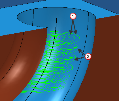
.Preview — Displays the pattern used to create the toolpath.
Draw — Select to display the preview pattern.