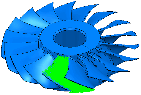
Use the Blade finishing page to specify different parts of a blisk or impeller and select the number of blades that you want to machine.
Blisk definition
Hub — Select the Level or Set that defines the hub geometry from the list.
Shroud — Select the Level or Set that defines the initial unmachined stock geometry from the list.
Fillets — Select the Level or Set that defines the fillet geometry from the drop-down list. All the fillets must also be in the Level or Set that defines the blade.
Since entities can be in only one level (but can belong to many sets) if levels are used to define the blade, then a set must be used to define the fillets. The fillet surface must belong to both the level defining the blade and the set defining the fillet.
Blades
Left blade — Select the Level or Set that defines the left blade (and any fillet) geometry from the list.
The left blade must be positioned clockwise from the right blade. So the left blade is the blade on the left when viewed looking into the gap that will be machined, in the direction of the central axis, with the Z axis of the active workplane pointing upwards.
Right blade — Select the Level or Set that defines the right blade (and any fillet) geometry from the list.
The right blade must be positioned anticlockwise from the left blade. So the right blade is the blade on the right when viewed looking into the gap that will be machined, in the direction of the central axis, with the Z axis of the active workplane pointing upwards.
Splitter Blade — Select the Level or Set that defines the splitter blade (and any fillet) geometry from the list.
Machine — Select the number of blades you want to machine.
-
One blade — Select to area clear between the two selected blades.
-
All blades — Select to area clear the whole blisk.
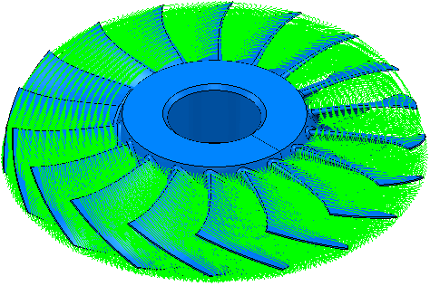
Total number — Enter the total number of blades on the blisk.
Calculate — Click to automatically calculate the Number of blades on the blisk.
Tolerance — Enter a value to determine how accurately the toolpath follows the contours of the model.
Thickness — Enter the amount of material to be left on the part. Click the
Thickness
 button to separate the
Thickness
box in to
Radial thickness
button to separate the
Thickness
box in to
Radial thickness
 Axial thickness
 . Use these to specify separate
Radial and
Axial thickness as independent values. Separate
Radial and
Axial thickness values are useful for orthogonal parts. You can use independent thickness on sloping walled parts, although it is more difficult to predict the results.
. Use these to specify separate
Radial and
Axial thickness as independent values. Separate
Radial and
Axial thickness values are useful for orthogonal parts. You can use independent thickness on sloping walled parts, although it is more difficult to predict the results.
Radial thickness — Enter the radial offset to the tool. When 2.5-axis or 3-axis machining, a positive value leaves material on vertical walls.

Axial thickness — Enter the offset to the tool, in the tool axis direction only. When 2.5-axis or 3-axis machining, a positive value leaves material on horizontal faces.

 Component thickness — Click to display the
Component thickness
dialog, which enables you to specify the thicknesses of the different surfaces.
Component thickness — Click to display the
Component thickness
dialog, which enables you to specify the thicknesses of the different surfaces.
Stepover
 — Enter the distance between successive machining passes.

 Copy stepover from tool — Click to load the radial depth of cut from the active
tool's cutting data. The radial depth of cut is measured normal to the tool axis.
Copy stepover from tool — Click to load the radial depth of cut from the active
tool's cutting data. The radial depth of cut is measured normal to the tool axis.
 .
.
Stepdown
 — Enter the distance between different machining levels.
Copy stepdown from tool
— Click to load the axial depth of cut from the active
tool's cutting data. The axial depth of cut is measured along the tool axis.
.