Use the Optimised constant Z finishing page to create a constant Z toolpath on the steep portions of a model and 3D offset toolpath on the shallow portions.
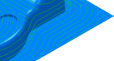
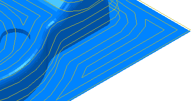
Spiral — Select this option to create a spiral path between two consecutive closed contours. This minimises the number of lifts of the tool and maximises cutting time while maintaining more constant load conditions and deflections on the tool.
Selecting Spiral converts this:
to this:
Closed offsets — When selected, creates the 3D offsets from the outside in. When deselected, creates the 3D offsets from the inside out.
It converts this:
To this:
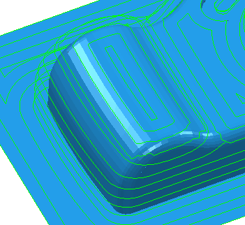
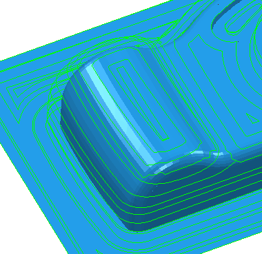
Smoothing — Select this option to smooth offsets of toolpath segments over the model.
Selecting the Smoothing option converts this:
to this:
Centreline — Select to include a pass over the centreline of toolpath corner junctions. This removes small cusps created at the junctions.
Centreline off.
Centreline on.
Tolerance — Enter a value to determine how accurately the toolpath follows the contours of the model.
Cut direction — Select the milling technology.
Select a Cut Direction from the following:
-
Climb — Select to create toolpaths using only climb milling, where possible. The tool is on the left of the machined edge when viewed in the direction of tool travel.

-
Conventional — Select to create toolpaths using only conventional or upcut milling, where possible. The tool is on the right of the machined edge when viewed in the direction of tool travel.

- Any — Select to create toolpaths using both conventional and climb milling. This minimises the tool lifts and tool travel.
Thickness — Enter the amount of material to be left on the part. Click the
Thickness
 button to separate the
Thickness
box in to
Radial thickness
button to separate the
Thickness
box in to
Radial thickness
 Axial thickness
 . Use these to specify separate
Radial and
Axial thickness as independent values. Separate
Radial and
Axial thickness values are useful for orthogonal parts. You can use independent thickness on sloping walled parts, although it is more difficult to predict the results.
. Use these to specify separate
Radial and
Axial thickness as independent values. Separate
Radial and
Axial thickness values are useful for orthogonal parts. You can use independent thickness on sloping walled parts, although it is more difficult to predict the results.
Radial thickness — Enter the radial offset to the tool. When 2.5-axis or 3-axis machining, a positive value leaves material on vertical walls.

Axial thickness — Enter the offset to the tool, in the tool axis direction only. When 2.5-axis or 3-axis machining, a positive value leaves material on horizontal faces.

 Component thickness — Click to display the
Component thickness
dialog, which enables you to specify the thicknesses of the different surfaces.
Component thickness — Click to display the
Component thickness
dialog, which enables you to specify the thicknesses of the different surfaces.
Stepover — Enter the distance between successive machining passes.
-
 Copy stepover from tool — Click to load the radial depth of cut from the active tool's cutting data. The radial depth of cut is measured normal to the tool axis.
-
 Edited — When displayed, shows value entered by you (or another user). Click
to change this value to the automatically calculated value.
Edited — When displayed, shows value entered by you (or another user). Click
to change this value to the automatically calculated value.
-
 Stepover — Enter the distance between successive machining passes.
If you enter a Stepover value, then
changes to
.
-
 Cusp height — Enter the maximum cusp height and use this value to determine the stepover.
PowerMill calculates the stepover value to give a cusp height of the machining tolerance using the current tool, when machining a plane inclined at 45
Cusp height — Enter the maximum cusp height and use this value to determine the stepover.
PowerMill calculates the stepover value to give a cusp height of the machining tolerance using the current tool, when machining a plane inclined at 45 . This is the worst case cusp height for any given tolerance.
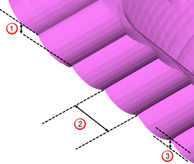
 Stepdown
 Stepover
 Cusp height
For more information see Linkage between stepover and cusp height.
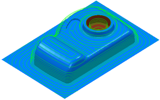
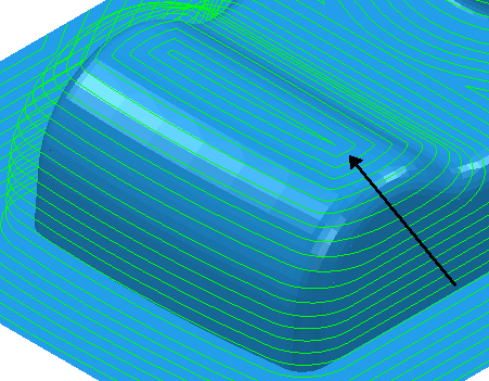
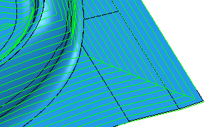
Use separate offset stepover — Select to have different stepover values for the steep and shallow areas. The Shallow stepover must be greater than or equal to the Stepover. When you set a Shallow stepover the Stepover box becomes the Steep stepover.
Looking at the camera.ttr from the Examples directory, you can see the effect of having a different stepover on the steep and shallow portions.
It converts this:
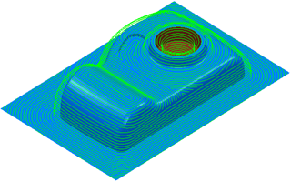
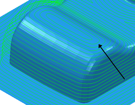
To this: