Use this option to apply thickness shading to your model. Thickness shading enables you to visualize the thickness of solids. This is useful for identifying thin regions of a model.
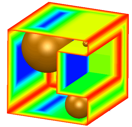
The thickness is measured by a ball inside the solid that is as large as possible without passing through any surface. As this ball rolls around inside the solid, it grows or shrinks as appropriate to fill the available space. The front face of the model below is cut away to show the measuring ball rolling around inside.
To use Thickness shading:
- Select the solid model.
- Click Visualisation tab > Shading panel > Thickness.
There will be a pause whilst the thicknesses are calculated; the length of time taken will depend on the size of the model.
- Use the Thickness Colour Scale dialog to dynamically rescale the colour thickness display:
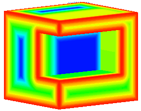
- Maximum thickness — Regions of the model that are thicker than the value shown in this box are displayed in blue. Adjusting this value using the slider changes the colouring of the model.
-
Minimum thickness — Regions of the model that are thinner than the value shown in this box are displayed in red. Adjusting this value using the slider changes the colouring of the model.
Intermediate thicknesses are represented according to the colour scale in the dialog.
-
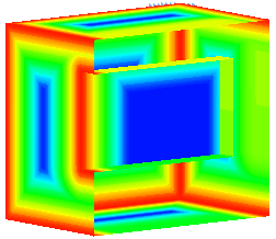
Make Sections — You can create dynamic wireframe sections of the areas of the model.
Before creating the sections, ensure that you have the relevant plane defined. The plane through which the sections are created is either the active workplane (if selected), or the plane of the graphics window when you click Make Sections.
Selecting Make Sections displays the Dynamic Sectioning dialog. The position of the section can be varied using the slider on the dialog. In the example on the right, the slider was set at 50%.
The colour displayed at each point on the surface of the solid represents the diameter of the ball when it touches that point: