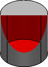
Use Dynamic Sectioning to take sections through your model. Use the sliders to move the clipping planes backwards and forward through the model. This lets you view the interior detail of the model.
The orientation of the front and back clipping planes is defined by selecting an Axis from the drop-down list in the Dynamic Sectioning dialog.
To use Dynamic Sectioning:
- Shade your model.
- If you have more than one view of your model displayed, click the view in which you want to move the section plane.
- Click Visualisation tab > Model panel > Dynamic Sectioning.
- Use the
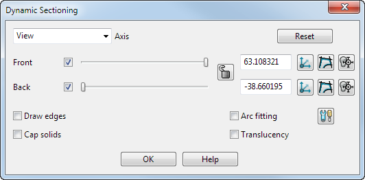
Dynamic Sectioning dialog to dynamically take sections through your model:
- Select the
Axis
from the drop-down list. This determines the orientation of the
Front and
Back planes.
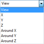
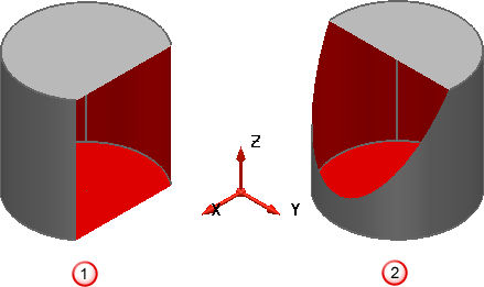
Around Y means rotate the clip plane around the Y axis of the world or active workplane. This is used for circular items that are centred on the workplane or world origin. In this case, the clip plane will give views of the cross section at particular angles.
 Y axis selected.
 Around Y axis selected.
- Specify the clipping planes to be used by selecting Front, Back or both.
- Holding down the left mouse button, drag the mouse to move a slider along. As you move the slider, the position of the sectioning plane is moved to display a section through the model.
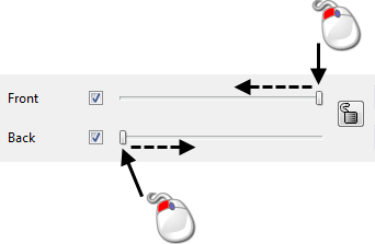
If necessary, click Reset to reset the clipping planes to the default position for the current view.
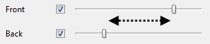
- Click
 to lock the clipping planes, so that the
Front
and
Back
planes maintain the same relative distance.
to lock the clipping planes, so that the
Front
and
Back
planes maintain the same relative distance.
 indicates that the planes are locked.
- If necessary, change the distance of the Front or Back plane from the origin.
- If required, click
 to create a workplane on the clipping plane. There are separate buttons for the
Front
and
Back
planes.
to create a workplane on the clipping plane. There are separate buttons for the
Front
and
Back
planes.
- You can also click
 to position the front and back planes at a position chosen using the
Intelligent cursor.
to position the front and back planes at a position chosen using the
Intelligent cursor.
- Click
 to create wireframe of the intersection of the model and the clipping plane
 . There are separate buttons for the
Front
and
Back
planes.
. There are separate buttons for the
Front
and
Back
planes.
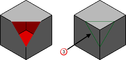
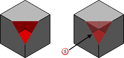
- The following options determine the appearance of the clipped plane:
Draw edges — Select this option to draw the edges of the section, as shown in
 .
.
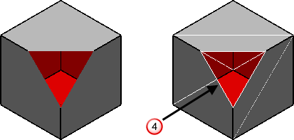
Translucency — Select this option to draw the section translucent, as shown in
 .
.
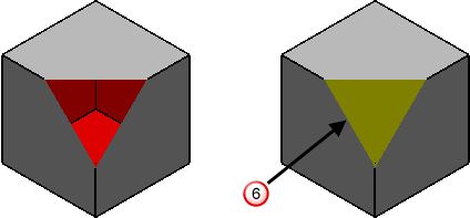
Cap solids — Select this option to display a cap on the solid where it intersects with the clipping plane
 .
.
- Select the
Arc fitting option to automatically apply arc fitting to any curves created using the dialog. You can also click the
Arc fitting options
 button to open the
Arc Fitting dialog.
button to open the
Arc Fitting dialog.
- Click Close to remove the dialog and reset the clipping planes.