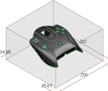
A block is automatically created around the selected object, unless you entered the Mold Die Wizard with a block already defined. The block size can be specified using either absolute or relative values. The wizard contains an image of the part as shaded and the block as wireframe. You can also rotate, zoom and pan this image using the mouse.
- Specify the block size using absolute or relative values:
- Use the
Absolute
tab to specify the height of the block using absolute values:
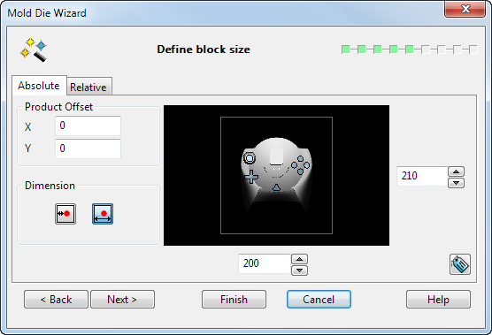
Product Offset — Enter values in the X and Y text box to offset the product centre from the block centre.
Dimension
 — Select this option to set the minimum land dimensions when you enter values in the boxes. This is the minimum distance between the product and the block.
 — Select this option to set the overall width and length of the block when you enter values in the boxes.
 — Use the arrows on these boxes to define the width and length of the die block. You can also type absolute values into the boxes
 — Display/hide dimension name labels on the model in the
PowerShape graphics window. The dynamic dimensions appear the same size on the screen, regardless of the zoom factor.
— Display/hide dimension name labels on the model in the
PowerShape graphics window. The dynamic dimensions appear the same size on the screen, regardless of the zoom factor.
- Use the
Relative tab to specify the width and length of the block by altering the distance between a known reference point and a block edge:
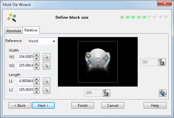
Reference — The reference point is marked with a yellow star. The available reference points are the World or Active workplane, or Product Centre. Active is the default reference point.
Width
W1 — The distance between the reference point and the nearest block edge.
W2 — The distance between the reference point and the furthest block edge
 —
W1 and
W2 can both be set using the mouse. Click
button and then use the mouse to snap to points on construction lines or other objects.
—
W1 and
W2 can both be set using the mouse. Click
button and then use the mouse to snap to points on construction lines or other objects.
Length
L1 — The distance between the reference point and the nearest block edge.
L2 — The distance between the reference point and the furthest block edge
—
L1 and
L2 can both be set using the mouse. Click
button and then use the mouse to snap to points on construction lines or other objects.
— Use the arrows on the two boxes to define the width and length of the die block.
 — The block length or width is currently unlocked. Click this button to lock the block length or block width.
 — The block length or width is currently locked, so the locked dimension will stay constant and you can alter the block position relative to the product. Click this button to unlock the block length or block width.
— Display/hide dimension name labels on the model in the
PowerShape graphics window. This replaces the
Show labels
option box from previous versions. The dynamic dimensions have been modified so that they appear the same size on the screen, regardless of the zoom factor.
— The block length or width is currently locked, so the locked dimension will stay constant and you can alter the block position relative to the product. Click this button to unlock the block length or block width.
— Display/hide dimension name labels on the model in the
PowerShape graphics window. This replaces the
Show labels
option box from previous versions. The dynamic dimensions have been modified so that they appear the same size on the screen, regardless of the zoom factor.
- Use the
Absolute
tab to specify the height of the block using absolute values:
- Click Next to display the Create split surface page to create the split surface. Any surfaces you provide that lie outside the die block will be removed automatically. If, at a later stage of the wizard, you return to the Define block size page and change the width, length or origin, the original, untrimmed, surfaces are displayed.