Use the Surfaces page of the Options dialog to control the default settings for surfaces within models:
- Click File > Options > Application Options > Object > Surfaces.
- Specify the default settings for creating surfaces using the following options:
- Trimming — Select this option to trim surfaces. Trimmed surfaces give a realistic shape. Untrimmed surfaces require less computer graphics processing, reducing screen redraw times. However, they can make the model confusing to look at.
- Draw surface orientation mark — Select this option to mark a surface’s outer face. Deselect this option to redraw complex models faster.
- Display normals for multiple surfaces — Select this option to show surface normals when you select multiple surfaces.
- Default draft angle — Enter the default angle to use when you create draft surfaces.
- Longitudinal detail lines per patch — When you select a surface for editing, additional grey detail lines are displayed to indicate the surface shape. Enter the number of detail lines between each pair of longitudinal curves. Enter 0 to disable detail lines.
- Lateral detail lines per patch — When you select a surface for editing, additional grey detail lines are displayed to indicate the surface shape. Enter the number of detail lines between each pair of sectional curves. Enter 0 to disable detail lines.
- Default fillet radius — This sets the fillet radius used by default when creating fillet surfaces.
- Keep pcurves generated by filleting — Select this option to keep the pcurves when Trim is deselected on the Fillet Surface dialog.
- Keep pcurves generated by limiting —Select this option to keep the pcurves when generated by limiting. No pcurves are generated if Trim both is deselected on the Limit selection dialog.
-
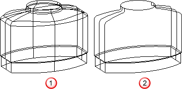
Suppress internal lines on surfaces — Select this option to only draw the laterals and longitudinals:
- on the surface edges;
- in the direction where the surface is closed;
- along a discontinuity in a surface;
- on a single selected surface.
Deselect this option to draw all the laterals and longitudinals on the surfaces.
This option only applies to wireframe view.

 Suppress internal lines on surfaces option is deselected.
 Suppress internal lines on surfaces option is selected.
-
Suppress internal lines on surfaces when shaded — This suppresses the drawing of internal lateral and longitudinal lines when shaded for clarity and efficiency.

 Suppress internal lines on surfaces when shaded option is deselected.
 Suppress internal lines on surfaces when shaded option is selected.
- Suppress internal lines on surfaces in solids —This allows you to set whether you want the internal lines to be drawn on surfaces in solids. If selected, internal lines are not drawn.
- Suppress internal lines on surfaces in components —This allows you to set whether you want the internal lines to be drawn on surfaces in components. If selected, internal lines are not drawn.
- Suppress detail on large surfaces — This allows you to set whether you want the detail lines to be drawn on single selected surfaces. If selected, detail lines are not drawn in a particular direction when there are more than 15 surface curves in that direction.
-
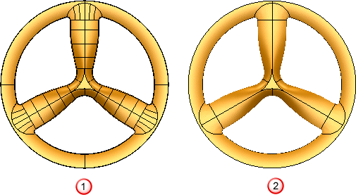
Draw continuous interior laterals on NURBS — Select this option to display the interior laterals on a NURBS surface.
By default, this option is deselected, so only surface curves at discontinuities and surface edges are displayed.

 Draw continuous interior laterals on NURBS option is deselected.
 Draw continuous interior laterals on NURBS option selected.
You can only click curves when they are displayed. If the curves are not displayed, use the (Surface Tools) Manage tab > Selection panel options to select them.
-
Minimum visible region (pixels) — This tolerance is set to
Automatic by default, but also provides a range of fixed values from 1 to 10.
When finding the core and cavity separation for a mold, the program looks at the model from the top and bottom (along the Z axis). Any surfaces which are visible in either direction are assumed to be part of either the core or cavity of the mold.
When calculating the separation, the surface is covered with triangles, however small gaps cannot be totally eliminated. Consequently, tiny areas (of an otherwise invisible surface) can be seen through these gaps. This option allows you to tell the core/cavity separation algorithm to ignore gaps (or other holes) of less than a set size.
- Use the
Primitives options for creating primitives (such as blocks and cylinders), extrusions and revolutions:
- Create as NURBS — Select this option to create the primitives (such as blocks and cylinders) as NURBS surfaces.
-
Convert all surfaces to Power Surfaces — This option affects the behaviour of the Home tab > Utilities panel > Convert > Surface command. It controls how primitive, morph or other special surfaces (other than NURBS or Power Surfaces) are converted.
Select this option to convert all types of surfaces to a Power Surface.
Deselect this option to convert the surface to a NURBS or Power Surface, according to the type of surface on which it is based.
- Keep wireframe (extrusions and revolutions) — Select this option to automatically keep the wireframe in the model. Deselect this option to remove the wireframe from the model. You can add the wireframe to the model again using the Create a copy of the sketch option on Sketch tab of the dialog for the extrusion or revolution. The dialog is displayed by double clicking the object.
- Create extrusions normal to planar base — Select this option to keep the extrusion normal to the planar base, when creating an extruded surface/solid using a planar base. Otherwise the extrusion is in the positive direction of the axis normal to the principal plane.