Use the options on the Primitives from Points dialog to control the shape and type of geometry that you want to create:
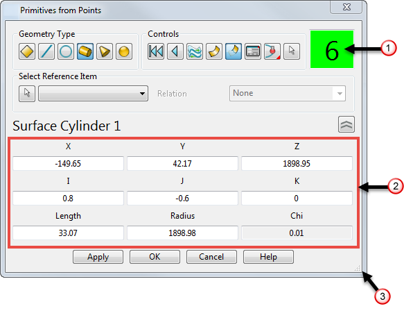
Geometry Type — Use the options from this area to define the shape of the geometry you want to create from the probed points.
-
 — Select this option to fit a surface plane to the probed points.
-
 — Select this option to fit a wireframe line to the probed points.
-
 — Select this option to fit a wireframe arc to the probed points.
-
 /
/ — Select this option to fit a surface or solid cylinder to the probed points.
-
 /
/ — Select this option to fit a surface or solid cone to the probed points.
-
 /
/ — Select this option to fit a surface or solid sphere to the probed points.
Controls — Use the options from this area to control how the geometry is created.
-
 — Click this button to clear all points.
-
 — Click this button to undo individual points.
-
 — Click this button to reverse the orientation of the surface. This button is only available if you create a surface.
-
 /
/ — Click this button to toggle between surface and solid creation.
-
 /
/ — Click this button to toggle surface trimming on or off. This button is only available if you create a surface.
-
 — Click this button to display the dialog to edit the appropriate primitive. For example, for a surface cylinder the
Cylinder
dialog is displayed.
— Click this button to display the dialog to edit the appropriate primitive. For example, for a surface cylinder the
Cylinder
dialog is displayed.
-
Probe Compensation — Select a probe compensation type, depending on the orientation of the probe from when the first point is taken, to adjust for the size of the probe:
 — Select this option to apply
Automatic compensation. This option will choose either
Inside or
Outside depending on the probe direction when the first point was taken, and the orientation of the created primitive.
— Select this option to apply
Automatic compensation. This option will choose either
Inside or
Outside depending on the probe direction when the first point was taken, and the orientation of the created primitive.
 — Select
None to apply no compensation.
— Select
None to apply no compensation.
 — Select
Inside if the probe is inside the part, to apply compensation outwards.
— Select
Inside if the probe is inside the part, to apply compensation outwards.
 — Select
Outside if the probe is outside the part, to apply compensation inwards.
— Select
Outside if the probe is outside the part, to apply compensation inwards.
-
 — Click the
Change active item button to select an item from the graphical window to become active. You can select any primitive surface, primitive solid, arc, or line, and edit it using the available options.
Note: You can use the Change active item option to select items that were not created in the current Primitives from Points session. However you cannot edit the points of these items. The Chi value is not displayed and the number of probed points display
— Click the
Change active item button to select an item from the graphical window to become active. You can select any primitive surface, primitive solid, arc, or line, and edit it using the available options.
Note: You can use the Change active item option to select items that were not created in the current Primitives from Points session. However you cannot edit the points of these items. The Chi value is not displayed and the number of probed points display shows zero and has a darker background colour.
— This displays the number of points you have currently probed.
Select Reference Item — Use the options in this area to select a primitive object to use as a reference item, and its relationship to the geometry you want to create.
-
 — Click the
Select reference item button then select a primitive on your model to set it as the reference item. The selected primitive is added to the drop-down list.
— Click the
Select reference item button then select a primitive on your model to set it as the reference item. The selected primitive is added to the drop-down list.
-
Relation — Use the options in the drop-down list to control the relationship between the reference item and the new geometry:
- None — The reference item has no relationship with the new geometry.
- Coplanar — The base of the new geometry is defined to lie in the XY plane of the reference item's workplane.
- Concentric — The workplane of the new geometry is defined to match the workplane of the reference item.
- Axis aligned — The sides of the new geometry are defined to run parallel to either the X or Y axis of the reference item's workplane.
- Parallel — For lines only, the line is defined to run parallel to the reference line.
- Perpendicular — For lines and surface planes only, the new geometry is defined to run perpendicular to the reference items workplane.
Note: When the Coplanar, Concentric or Axis aligned options are selected the Offset area is displayed. Enter the Height above the reference item, or select As Probed to automatically calculate the height from the probed points. Enter values into the Azimuth and Elevation fields to define the angular offset of the new geometry from the reference item.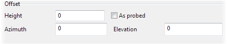
 — This area contains a number of fields that depend on the type of item being created or edited. They define the size and position of the geometry. Enter values into the fields to modify your new geometry. If the item was created by probing, the
Chi value describes how well the created geometry fits the probed points. A smaller Chi value indicates a closer fit.
— This area contains a number of fields that depend on the type of item being created or edited. They define the size and position of the geometry. Enter values into the fields to modify your new geometry. If the item was created by probing, the
Chi value describes how well the created geometry fits the probed points. A smaller Chi value indicates a closer fit.
 — Use this handle to increase the size of the dialog. The text and icons scale with the size of the dialog, enabling you to read the dialog from a distance.