Use the Specify Electrode Blank page to specify the blank used to manufacture the electrode from. This topic covers the options displayed when the workpiece is an active solid, and your model also contains a pre-selected electrode solid with a base.
The base, formed by the top part of the blank, can either include or interact with an electrode holder. If you are creating a vector-burn electrode that may require a specialised holder, click
 to specify details of the vector burn, before specifying the blank. To simulate the electrode burn motion, click
 .
.
- Select a standard blank from the list. The blanks available are those which fit the dimensions of the electrode.
If you select a standard blank, its dimensions are automatically added to the Electrode Wizard and you can't change the values.
- Select User Defined to create your own blank:
- Click the
 /
/ button to specify whether to create a rectangular or circular blank.
- Enter values in the following boxes to specify the dimensions of the blank:
- Length — To specify the length of a rectangular blank.
- Width/Diameter — To specify the width of a rectangular blank, or the diameter of a circular blank.
- Height — To specify the height of the blank.
Tip: Height, Thickness, and Base Ht. are related. If you change one value, another value also changes. For further details, see Tips for creating electrodes. - Select an option from the Material list to specify the material of the blank. Choose from copper or one of three grades of graphite:
Name
Grade
Grain size
Graphite-1
High
< 3
 m
m
Graphite-2
Medium
3-10
m
Graphite-3
Low
> 10
m
These grades are used by the Electrode Family page to determine the recommended values for the undersizes.
Tip: You can add new materials to this list using the materials alias file. - Enter a value in Base Ht. to specify the height of the base.
- Enter a value in Thickness to specify the minimum Z thickness that is machined from the blank. This value represents the amount of waste; by setting a small Thickness, you can minimise the waste material and the amount of machining required. Only use a zero thickness if the blank has been pre-ground to the desired surface finish.
- Click
 to automatically rotate the electrode blank to the best position. Alternatively, enter a value in Rotation to specify the angle by which the blank rotates around the Z axis.
Tip: If you rotate the blank, you may be able to specify a smaller blank for the electrode. This can reduce the amount of material wasted and also save on machining time.
to automatically rotate the electrode blank to the best position. Alternatively, enter a value in Rotation to specify the angle by which the blank rotates around the Z axis.
Tip: If you rotate the blank, you may be able to specify a smaller blank for the electrode. This can reduce the amount of material wasted and also save on machining time. - Select an option from the Datum list to specify the face of the electrode where the datum lies, then use the radio buttons to choose where on the face the datum is positioned. The datum determines the position of the electrode in the model and is used for machining purposes.
- Enter X, Y, and Z coordinates to specify the position of the datum relative to the current workspace. If you change these values, the base of the electrode moves relative to the datum. For example:
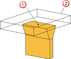
 Datum in the middle of the bottom face
 Electrode base
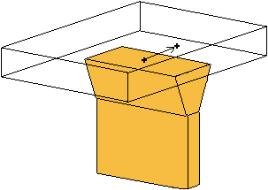
Move the datum as shown below:
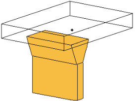
The base moves too:
 The Z coordinate is available only if you select Base Top or Base Bottom from the Datum list. If you change the Z value, the height of the base changes.Note: For EDM setup, the actual position values are rounded to the nearest 0.1mm/0.01 inch/10 thousandths.
If you click
 to exit the wizard, the electrode and base are created as separate solids and remain selected. You can modify the solids, add them together, and enter the Electrode Wizard again. This registers the solids as an electrode.