You can specify how Power Features are applied using the Power Features Summary dialog. The following example shows how you can use the dialog to control the intersection of the target components with the source components:
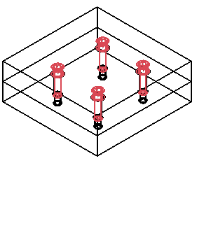
- Create a plain moldbase and use Assembly tab > Component panel > Wizard to place some screws. The example below uses four Hasco Z31 screws.
- Select Assembly tab > Power Features panel > Generate.
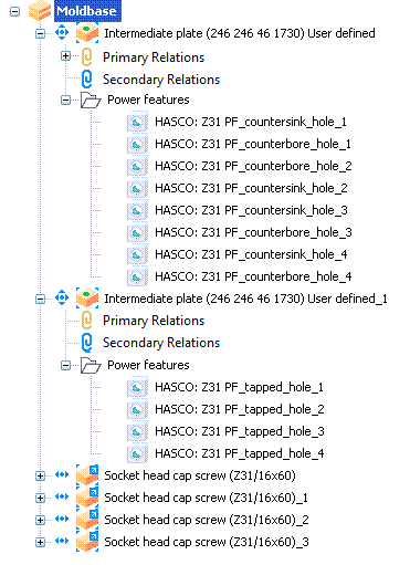
Power Features are generated automatically, and the model and the assembly tree are updated:
- Click Assembly tab > Power Features panel > Summary.
The Power Features Summary dialog is displayed.
- Select a Source Component from the drop-down list, and use the options on the dialog to make any other changes.
- Click OK to apply your changes and close the dialog.