The relationship between a solid feature and a solid is specified using the Solid Feature Relationship dialog. To display the dialog, select  on the appropriate solid feature dialog.
To create arelationship between a solid feature and a solid, you need to specify:
- a keypoint on the solid.
- a keypoint on the feature.
- the distance between the keypoints.
To specify a keypoint on the solid:
- Click
 to attach a workplane to the cursor and display the keypoints on the solid as blue circles.
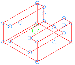
- Select the keypoint. The unselected points are removed, leaving only the selected keypoint.
The
 changes to a
  to indicate the relationship workplane is correctly specified.
To specify a keypoint on the feature:
- Click
 to display the keypoints on the feature as blue circles.
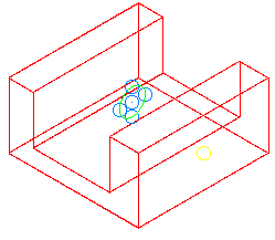
The keypoints that are displayed depend on the feature:
- Solid cut and solid boss — the keypoints are points on the sketch and the average centre point of the sketch.
- Boolean features — the keypoints are keypoints on the secondary solid.
- Hole features — the keypoint is always the origin point of the hole. The point button is unavailable because it cannot be changed.
- Pocket/Protrusion features — the keypoint is always the origin point of the pocket/protrusion. The point button is unavailable because it cannot be changed.
- Select the keypoint. The unselected points are removed, leaving only the selected keypoint.
The
changes to a to indicate the keypoint on the feature is correctly specified.
To specify the distance between the keypoints:
The X, Y and Z values that specify the distance between the keypoints on the solid and the feature are shown:
- graphically as dimensions on the model.
- as values on the dialog. The values can be numbers or parameters. If you alter these values, the feature moves.