Use this page to specify the extension distance of the puller.
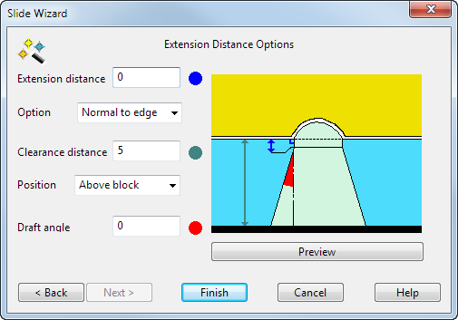
The graphic shows where the three values are calculated.
- Use the options on the page to define the extension of the puller:
Extension distance — The extension of the core puller from the undercut region.
Option — Choose an entry in the list to specify how the core puller is extended:
- Normal to edge — The extension is perpendicular to the edge of the undercut region.
- Surface internals — The extension is along the direction of the laterals/longitudinals on the underlying surface of the undercut region.
- Vertical — The extension is aligned vertically along the Z axis. The internal curves of the extension are aligned with the Z axis, but the extension itself is still tangent continuous to the undercut region. For this reason, this option is not suitable for extending faces which lie flat in the XY plane.
Clearance distance — The distance of the core base from the selected Position option. It is measured along the Z axis.
Position — This is one of the following: Above block or Above extension.
Above block — The highest point of the solid from the XY plane.
Above extension — The highest point of the extension of the undercut face from the XY plane.
Draft angle — The angle on the extension of the core puller, excluding the part which extends from the undercut region. It is measured from the Z axis.
Preview — Displays the core puller in the model window using the values from the dialog. Change the values if necessary and click Preview again.
- Click Finish to create the core puller.