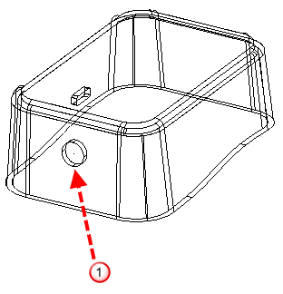
The following example will be used to show you how to use the
Slide Core wizard.
 indicates the undercut region
Before using the Slide Core Wizard:
- Click Wizard tab > Mode panel > Toolmaker On/Off to run Toolmaker.
- If necessary, create the die inserts using the
Mold Die
Wizard.
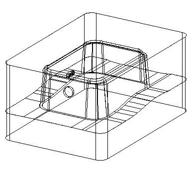
- Ensure the die inserts are watertight. To check if the die inserts are watertight, right-click the insert and select Make watertight from the context menu.
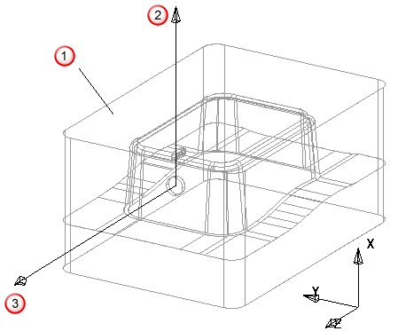
- Orient the workplane by pointing the X axis along the draw direction so it points towards the cavity and away from the core, and the Z axis points in the slide extraction direction.
Cavity is higher up the X axis than the core
 Draw direction
 Direction of slide extraction
- Create the contact profile (not needed for a core puller). This is an open composite curve; whose ends touch the split line of the die inserts. It lies on the solid that contains the undercut area.
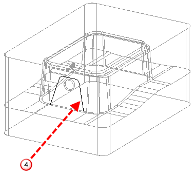
The contact profile
 forms the outer walls of the core.
The composite curve does not need to lie on the die insert. You can create a 2D composite curve on the XY plane. The wizard projects it onto the die insert along the Z axis to create the contact profile.
The Slide Core wizard can also automatically generate a contact profile.
An easy way to generate a contact profile is:
- Create a 2D composite curve of the outline of the core.
- Position the composite curve so that it is close to the undercut region.
- Create an extruded solid from the composite curve so it intersects with the appropriate die insert.
- Create a composite curve from the intersection of the extruded solid and the die insert.
- Limit composite back to the split line.
You are now ready to use the Slide core wizard.