A schedule from balloons is a table containing the coordinates of positions marked by pointers of balloons. It can be created from all balloon types except geometric tolerances, surface textures, weld symbols and point balloons.
If all the balloons present are snapped to components, a Bill of Materials is produced.
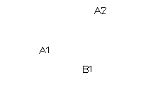
Three schedule balloons are given in the example below:

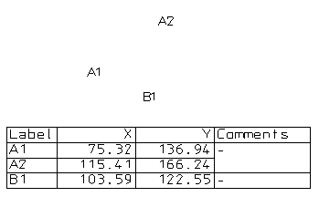
The following schedule is created for these balloons:

The coordinates of the pointers of the balloons are displayed in the schedule.
For schedule balloons, no pointer is visible. In this case, the pointer is the first position entered when you create the balloon.
If the pointer lies on a drawing or a model, then its coordinates are measured from the origin of the current workspace. If the pointer lies on a drawing view, then its coordinates are measured from the origin of the drawing view.
A comment column is also drawn in the schedule. Balloons A1 and A2 are from the same series, so the entries for their comments are merged.
By default, only the X and Y coordinates are displayed. To display the Z coordinate, turn on the Include Z coordinate option on the Schedule page of the Options dialog.
When you create a balloon by clicking its pointer on an object, such as the centre of a circle, the pointer's position and the centre of the circle become related. If you move the centre of the circle, the coordinates of the balloon update in the schedule.
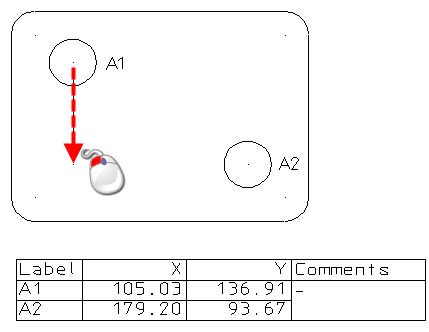
In the example below, balloon A1 is related to the centre of the circle on its left. We move the circle downwards:

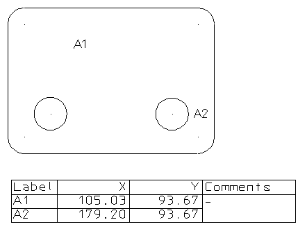
When the circle is moved, the entry in the schedule for A1 updates too:
