To change the appearance and contents of the component drawings, you need to edit the component drawing template. The component drawing template must be in your shareddb before it can be modified.
The component drawing template can be added to your shareddb by:
- Creating a component drawing with the supplied component template.
- Importing the template from the
C:\Program Files\Autodesk\PowerShapexxxxx\file\assembly
where xxxxx is the version number of PowerShape and C is the disk on which PowerShape is installed.
When the template is in your shareddb, you can modify the template as follows:
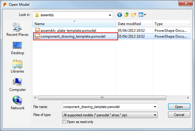
- Select File > Open > Model. From the list, select the component drawing template file and click
Open.
- Click Draft tab > Drawing panel > Open. From the list select the template you wish to modify and click
OK:

The following templates are included. By default, X indicates the size and is in the range 0 to 4 to reflect A0 to A4 sizes.
component_sheet_plate_X - plate components.
component sheet_rotational_X - rotational components.
component_sheet_userdefined_X - user-defined components.
component_sheet_X - other types of components.
- Use the techniques that are used to change Drawing Templates to customize the views, hole schedules, and table positions in the templates as follows:
- If text exists that starts Parameter table position, the parameter table is placed at that position. The maximum height of the table can be given by having End as the final part of that text item.
- For components with a trimmed length parameter, a table will be produced of the trimmed lengths if a text exists that starts Trimmed table position.
- If the component drawing template contains drawings prefixed with the following:
ga_sheet
shaded_ga_sheet
the appropriate drawings will be created if the Create GA Sheet or Create shaded GA Sheet option on the Component Drawing dialog is selected.