To create a addendum surface:
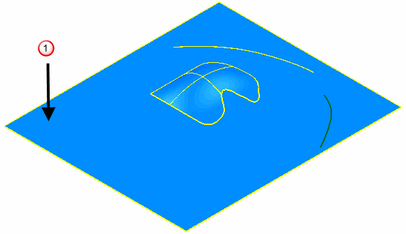
- Select the Binder surface and the surface that is to be used to create the addendum surface.
Note: This step is important as it is not possible to select the binder surface later.
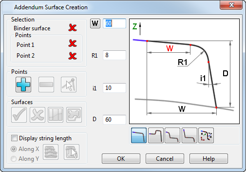
- Select Surface tab > Manufacture panel > Tooling > Addendum to display the Addendum Surface Creation dialog, with the Binder surface pre-selected.
- Use the options on the dialog to enter the settings to be used when creating the surface:
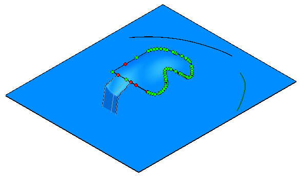
- Click OK to create the Addendum surface.
The options on the dialog are used as follows:
Selection
Use the options in this section to identify the surface and points that are to be used.
-
Binder surface
or
Blank holder surface. The Binder surface must be larger than the part and situated below the part. The Binder surface
 was selected before the dialog was displayed:
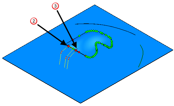
- Select
Point 1 to be used to create the addendum surface. The selection is indicated by
 on the following model.
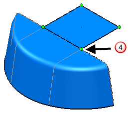
- Select
Point 2 to be used to create the addendum surface. The selection is indicated by
 on the following model:
Points
Use this section to add and delete points.
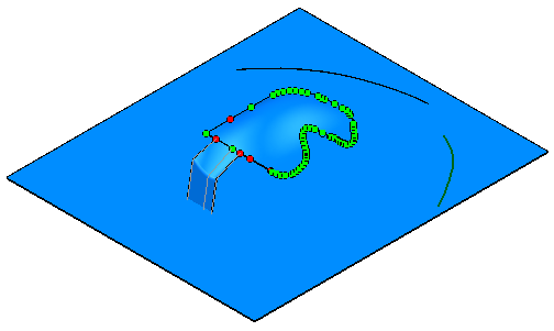
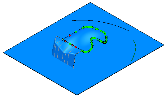
On the model, green points are required to hold the edge of the addendum onto the part. If you remove a green point, an overlap or a gap is created. Red points are redundant points; these can be deleted without problem.
To insert an additional boundary point:
- Click
 .
.
- Click the boundary curve where the new point is to be created.
To delete a point, or a selection of points from the boundary curve:
- Select the points.
- Click
 .
.
To see an alternative solution for a surface with sharp corners:
- Select

- Click
 and cycle through the possible solutions.
 to create the amended surface.
Selecting a profile
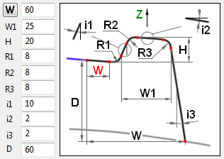
Use the profile buttons to select an appropriate profile.
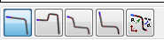
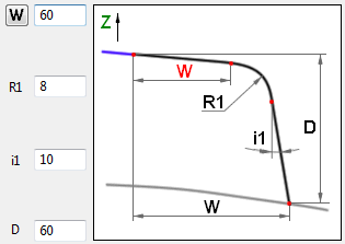
If the profile is blue, you cannot use the profile type you have selected. If the profile is yellow, the profile type you have selected can be used. The dimension options that are available are based on the profile you select. The Depth (D) is calculated automatically to ensure that the addendum surface intersects with the binder surface.
 — Selecting this profile makes the following dimension options available
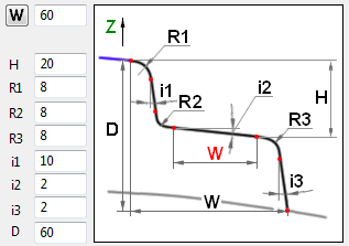
 — Selecting this profile makes the following dimension options available
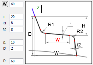
 — Selecting this profile makes the following dimension options available
 — Selecting this profile makes the following dimension options available
 — Opens the Parametric curve editor. Use the options in the Parametric curve editor to edit the selected profile. The buttons on the Parametric curve editor also appear in 2D curve editing.

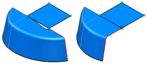
 — Click to toggle between black and red width. This provides two solutions using different widths but keeping the remaining parameters the same.
Surfaces
— Create the addendum surface.
 — Delete the currently selected addendum surface. You can select the addendum surface to delete by clicking on the surface itself, or by clicking on the points on the laterals. You can also delete the selected addendum surface using the
Delete key.
— Delete the currently selected addendum surface. You can select the addendum surface to delete by clicking on the surface itself, or by clicking on the points on the laterals. You can also delete the selected addendum surface using the
Delete key.
 — Click on any boundary point between the two surfaces you want to connect. Click to create the connected surface. You can delete the connection surface using the
button on the dialog or by using the
Delete
key.
— Click on any boundary point between the two surfaces you want to connect. Click to create the connected surface. You can delete the connection surface using the
button on the dialog or by using the
Delete
key.
 — The
Punch
Open
line is the intersection of the addendum surface and the binder surface and is typically a curve or a composite curve
— The
Punch
Open
line is the intersection of the addendum surface and the binder surface and is typically a curve or a composite curve
- Select Point 1 and Point 2.
- Select the curve or composite curve to be used as the PO line

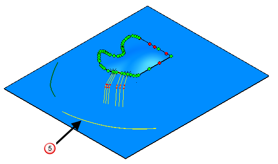
- Click
.
The laterals that are used when creating the addendum surface are extended to the PO line.
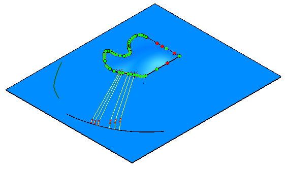
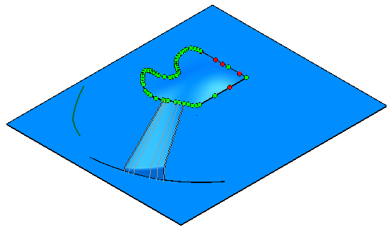
- Click
to generate the addendum surface.
String Length
- Click
Display string length to activate the string length functionality. This controls the way oblique strings are displayed.
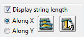
- Click Along X or Along Y to define the orientation of the oblique strings.
- Click on of the following:
-
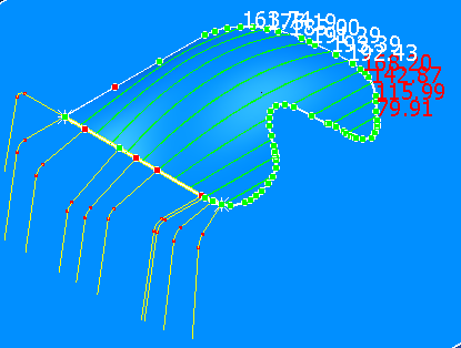
Area
to create 10 oblique strings with a sensible interval through all items (a main part + created addendum surfaces). The model below was created by selecting
Along X and
Area.
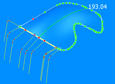
-
Point
to create an oblique string through a picked on an item point.
Pick a point.
The following model was created by selecting Along X and Point.
-
Area
to create 10 oblique strings with a sensible interval through all items (a main part + created addendum surfaces). The model below was created by selecting
Along X and
Area.