Attachment points help to define the placement and orientation for a component. When you select a component for placement on a drawing, you place it by its block origin (0,0) by default. You can switch from the origin to an attachment point before placing the component by pressing the spacebar or ENTER key. Attachment points define directional information for components that have an upstream and downstream direction associated with them (for example: check valves).
Attachment points are required to specify, label, and correctly apply end connections. They are used in components such as pumps and blowers to determine that the connections in a drawing represent the available connections on the real-world items. Inline components such as valves have attachment points that provide precise control over line connections. When you place an inline component on a schematic line, its attachment points ensure that the schematic line is properly broken.
Attachment points serve as the recommended connect points for a component. If you do not use attachment points, the extents of the block determine where the line is trimmed to connect to the component. It is recommended that you use attachment points in the symbols that you create. Also, do not remove or change the order of the attachment points in the blocks that are included with the program.
Define Attachment Points
You define attachment points in a block with the Block Editor and Point parameters. Each Point parameter that you want to use as an attachment point must follow a specific labeling convention, "AttachmentPoint" + [Numeric Suffix]. For example, the first attachment point for a block would be labeled AttachmentPoint1, the second attachment point would be labeled AttachmentPoint2, and so on.
If you are defining an attachment point in a block for a valve or inline instrument, also define the rotation angle of the end connection by using the labeling convention "AttachmentPoint" + [Numeric Suffix] + ":EndCode" + [Rotation Angle in Degrees].
For example, a block has a Point parameter with the label AttachmentPoint1:EndCode90 for one of its attachment points. The label AttachmentPoint1:EndCode90indicates that it is the first attachment point for the block and that the end connection at the attachment point is rotated 90 degrees. If you do not want to use end connections with a block for a valve or inline instrument, use the labeling convention "AttachmentPoint" + [Numeric Suffix].
Node points are added to all attachment points to make drawing and connecting lines easier. To snap to an attachment point on a component, you use the Node snap. The Node snap also snaps to a point object, dimension definition point, or dimension text origin contained in a block or drawing.
Orient Attachment Points
Most inline components, such as those on the Fittings and Valves tabs of the PIP tool palette, are horizontally oriented by default. Their attachment points fall on the X axis, following the flow of a horizontal line either to the left or right. Some components, however, are oriented by default along the Y axis. If you place such a component (for example: a flame arrestor) on a horizontal line, it automatically rotates to align with the line direction.
When you configure symbols for components, remember the following guidelines:
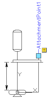
- The imaginary vector drawn from Attachment Point 1 (AP1) to Attachment Point 2 (AP2) defines the direction of the component.
- Most components are horizontally oriented, with the vector along the X axis.
- Some components, such as Flame Arrestors, have AP1 to AP2 along the positive Y axis. These components are vertically oriented.
- If the vector does not follow the X or Y direction, it is ignored.