To set the COG in the 3D Model
-
 In the Analysis Ribbon, click Edit COG.
 - In the drawing area, select one Plant 3D object (piping, structure, or equipment).
- Enter e (Edit).
- Specify a new COG location
- Enter n to (End).
Note: You can also enter COG in the properties palette.
To create a COG snapshot
Live COG does not need to be enabled to take COG Snapshot.
- In the drawing area, select piping, structure, or equipment. For example, select the Connected Line Number.
-
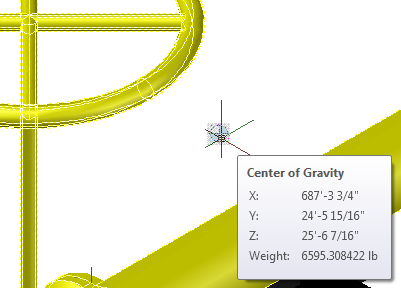
 In the Analysis Ribbon, click COG Snapshot. The COG glyph displays in the 3D model.
 - Hover over the COG snapshot glyph to display the rollover the tooltip.

If the COG glyph displays inside piping, you can set a wireframe or transparent visual style.