Edits the symbols that are used when creating isometric drawings. Sets default properties and text for Iso reference dimensions.
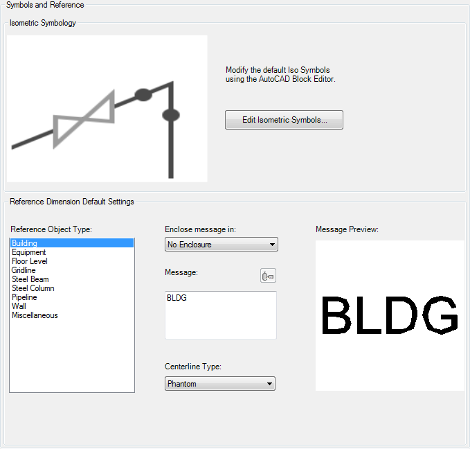
Isometric Symbols
Modifies symbols used when creating Iso drawings.
- Edit Isometric Symbols
-
Displays a list of blocks in the project Iso symbol library (IsoSymbolStyles.dwg).
Reference Dimension Default Settings
Sets values for new isometric reference dimensions added to the 3D model. After placement, these values can be modified in the properties palette.
- Reference Object Type
-
Lists Plant objects. When an Iso reference dimension is created in the 3D model to the object, the defaults assigned here are applied.
- Enclose Message In
-
Sets the default enclosure type to display in the Iso drawing.
- Message
-
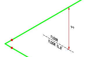
Specifies the default text to display in the isometric drawing. You can include property values for equipment, structure, or piping references. For example, FLOOR EL.# (StructurePlate.TOS) can display FLOOR EL# 12'.
-
 Select Class Property
 -
Adds a class property to the message. Enabled for external plant objects (equipment, structure, and piping).
Note: You can add additional text and include more than one property ( PlantObject.property ) if you enter text directly.For example, FLOOR EL.# (StructurePlate.TOS) can display FLOOR EL# 12' in the Iso drawing.
 Message properties (for example: tag numbers or column ID) are assigned when the Iso reference dimension is placed into the 3D model. If a property is not found, the value is left blank.
- Centerline Linetype
-
Specifies the default linetype such as Dashed ( _ _ _ _ _ _ _ _ _ _ _ _ _ _ _ _ _ ).
- Message Preview
-
Displays a preview of the isometric drawing text and enclosure.