Isometric reference dimensions allow you to document objects in the 3D model that are not part of the pipe line in Iso drawings.
A primary purpose of a reference dimension is to locate piping in the isometric drawing relative to a foundational element at the site. For example, the center of equipment such as a vertical tower.
A most common reference is a steel column or grid line.
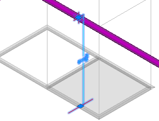
For example, you can reference a structure such as a beam. An Iso reference dimension is placed in the 3D model and displays a preview of the reference dimension that will be added to the Iso drawing. Select or highlight the Iso reference dimension to display the preview.
In the isometric drawing, dimensions to the referenced object are created. You can also specify the reference linetype and accompanying text.
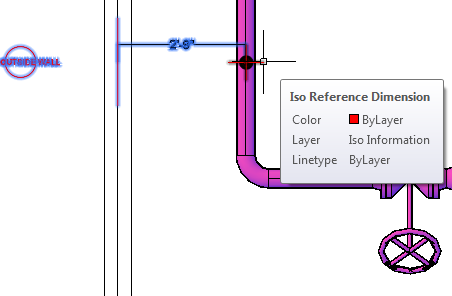
When not selected or highlighted the Iso reference dimension is hidden inside piping. It is similar to an Iso Message, but Iso reference dimensions have coordinate lines that extend a small amount outside piping.
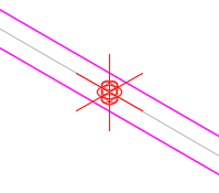 Wireframe view.
The lines allow you to select the Iso reference dimension in non-wireframe views.
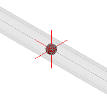 Visible in transparent piping.
Both Iso messages and Iso reference dimensions are created on the Iso Information layer.
Referenced Objects
Iso reference dimensions can reference plant objects, non-plant objects (AutoCAD line), or even no object (a location in space).
If a plant object is referenced, the initial settings of the Iso reference dimension are set intelligently. Plant objects in an xref are referenced intelligently.
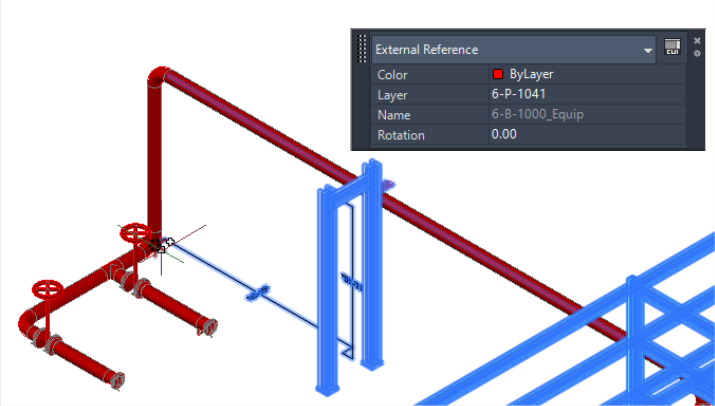 Reference to structure in an xref.
Iso reference dimensions are not associative. Regardless of initial settings, Iso reference dimensions are not linked to the referenced object. Once created, you can change Iso dimension reference type and values in the properties palette.
Isometric Reference Dimensions
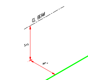 Reference to beam centerline.
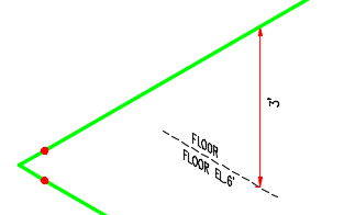
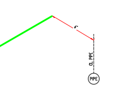
Reference to floor elevation.
Isometric reference dimensions allow you to document objects in the 3D model that are not part of the pipe line in Iso drawings.
An Iso reference dimension is placed in the 3D model and displays a preview of the reference dimension that will be added to the Iso drawing. Select or highlight the Iso reference dimension to display the preview.
For more information see: About Isometric Reference Dimensions and Iso Symbols and Reference Setup.
Iso Reference Dimensions (X Y Z)
You can set any combination of X Y and Z dimensions in the Iso drawing.
 Show X dimension only.
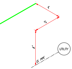 Show X Y and Z dimensions.
You can specify a skew dimension type that creates one dimension for the total distance.
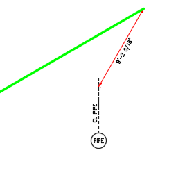 Skew dimension.
You can also create a locating dimension along piping to the Iso reference dimension location.
 Locating dimension.