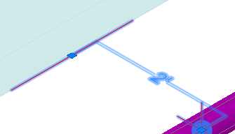
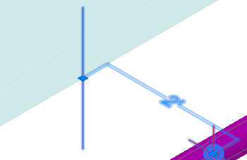
Configures isometric reference dimension objects in the 3D model
 Command entry:
properties
Command entry:
properties 
Isometric reference dimension options are set in the object properties palette.
Reference Object
Sets values for new isometric reference dimensions added to the 3D model. After placement, these values can be modified in the properties palette.
- Object Type
-
Lists external objects that can be referenced. Available types:
- Building
- Equipment (Equipment)
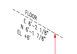
- Floor Level (Structure)
- Gridline
- Steel Beam (Structure)
- Steel Column (Structure)
- Pipeline (Piping)
- Wall
- Misc
Structure, equipment, and piping can include properties (for example: floor elevation) in the default message. You can set up properties in Project Setup in the .
- Centerline Direction
-
Sets the reference line direction in the isometric drawing.
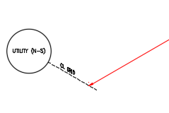 North-South.
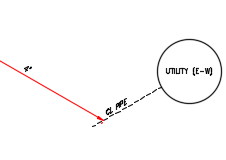 East-West.
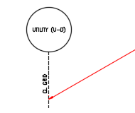 Up-down.
In the 3D Model, direction displays as a short line.
 North-South.
 Up-down.
- Centerline Linetype
-
Specifies the default linetype such as Dashed ( _ _ _ _ _ _ _ _ _ _ _ _ _ _ _ _ _ ).
- Enclose Message In
-
Sets an enclosure shape such as a rectangle or circle. You can set defaults and preview enclosure shapes in Project Setup in the Iso Symbols and Reference Setup pane.
- Message
-
Specifies text to display in the isometric drawing.
- Add Coordinate to Message
-
Adds the location to the text in the isometric drawing.
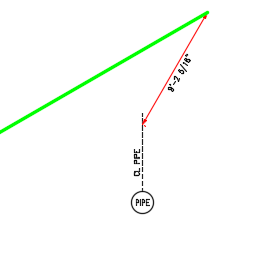
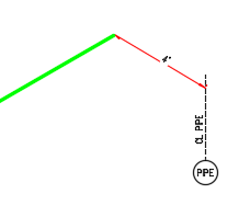
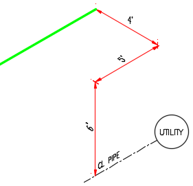
Reference Dimensions
Sets orthogonal or skew dimensions. For orthogonal dimensions you can specify which axis to include.
- Dimension Type
- Sets orthogonal or skewed dimensions.
 Skew dimension.
- X, Y, Z Dimension
-
Shows or hides dimensions in the Iso drawing.
 Show Y dimension.
 Show X Y and Z
- Show Locating Dimension
-
Locates the point on the pipe that the reference dimension refers to.
 Locating dimension.