The dialog box below enables defining the type of variability of compressive forces over the length of the analyzed member. The option is available after pressing an appropriate icon (for the direction y or z) in theBuckling length coefficient field located in the Member Definition - Parameters dialog box.
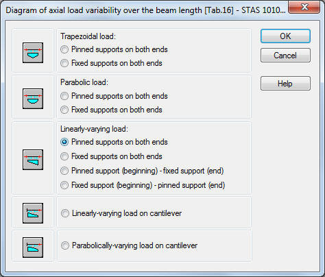
In the dialog box the user should choose one of the patterns of loading and fixing the member under analysis. The program will automatically determine values of compressive forces at the characteristic points on the member and will define the appropriate buckling lengths according to the formulas specified in Table 16. Take note that the pattern of fixing a member should be compatible to the buckling pattern defined in the Buckling Types dialog box. Otherwise, the program will not take account of the influence of the compressive force variability. For example, for a beam with pinned supports on both ends, select one of the following icons: 1, 3 or 5 from the top of the dialog box.