The option is used to determine the code parameters of a member type. The option becomes available by selecting the New member type option in the Member Type dialog box or by pressing the Parameters button in the Definitions dialog box.
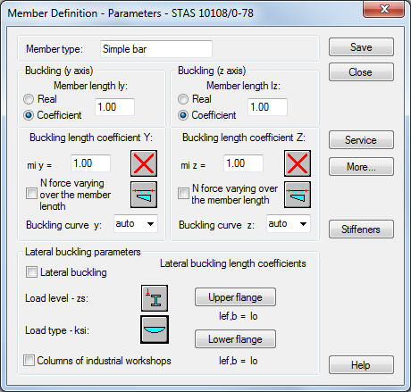
The Member type field is used to determine the name of a selected member type (any name of the member type may be typed here). The length of a member for the appropriate plane is defined in the Buckling (y axis) and Buckling (z axis) fields. There are two ways to determine this length:
- once the Real option is selected, the value entered is interpreted directly as member length
- once the Coefficient option is selected, the value is interpreted as the coefficient by which the real member length should be multiplied to obtain the required value. For instance, if the value 0.25 is entered, it means that the relevant member length equals 1/4 of the real length.
For simultaneous definition of several members whose actual lengths differ and e.g. additional supports are equally spaced, the second method mentioned is very convenient. If the set parameters are to be saved as a category, defining the length this way is necessary. Entering the value 1.0 guarantees that each member defined as Ly - using the category will have its actual length accepted.
Coefficients of the member buckling length in both directions may be determined in the Buckling Length Coefficient field. The actual member length (or the sum of the component member lengths) is automatically entered into the appropriate fields.
The buckling length coefficient depends on the end-support conditions of the member nodes in the buckling plane. The buckling length may also be defined in the Buckling types dialog box, that opens on pressing the icon representing the selected type of a buckling model. It includes typical schemes of the member support; when one is selected, the coefficient value is accepted or calculated automatically.
The icons in the dialog box are divided into two groups: the first one comprises typical (code) methods of the member support and the corresponding values of buckling coefficients, whereas the other consists of icons representing options used for calculation of the buckling coefficient for columns of multi-story frames.
Selection of the N force varying over the member length option enables determining the buckling length of members in which the value of a compressive force varies along the member length. Pressing the icon located next to the option opens an additional dialog box Diagram of axial load variability over the beam length, where the user selects one of the load patterns for a member in compliance with the Table 16 of the code.
The program automatically defines relevant buckling curves of a member depending on the section type, according to the table 42. However, if the user wants the program to perform calculations for a different curve than that defined automatically, then a name of that curve (A, B or C) may be specified in the Buckling curve y(z) field.
Buckling is considered in calculations always when a compressive force acts on the member, even if it is negligible in comparison to other internal forces. The program does not perform on its own a separate analysis that would determine if buckling effects should be disregarded or not. If the user wants to exclude buckling effects from the calculations, the last icon must be chosen. If pressed, buckling will be disregarded in the calculation process.
The Lateral Buckling Parameters field enables the user to select options applied in verification of the lateral buckling of a member: load level, load type and lateral buckling length coefficient for the upper and lower flanges. The user may also emphasize that the analyzed member is a column of an industrial hall. Pressing the appropriate icon opens the dialog box for definition of the relevant parameters.
If the Lateral buckling option is switched on, the code requirements concerned with the lateral buckling are taken into account in member calculations. In order to determine the lateral buckling conditions, it is also necessary to define the load level (load on the lower or upper flange) as well as the load type.
Lateral buckling calculations require that the user should specify for a member the distance between sections protected against torsion, the so called lateral buckling length. Since it is possible to fix the upper and lower flanges separately and there may be compressive stresses in the upper or lower flange for different load cases, two buckling lengths are distinguished. Therefore, the user determines a coefficient by which the base length of a member should be multiplied to obtain the lateral buckling length. The actual length of a member is assumed as the base length. The coefficient value may be entered directly or by selecting an icon representing a typical case of member fixing for which the coefficient will be chosen automatically.
Pressing the More button opens an additional dialog box for definition of the remaining parameters of a member type, described in the code, such as: equivalent moment coefficients, section parameters, etc.
Pressing the Service button opens an additional dialog box for definition of member type parameters (limit displacements, camber).
Pressing the Stiffeners button opens an additional dialog box for definition of transverse stiffeners located along the member length.
Pressing the Save button adds the member type with a defined name and parameters to the list of previously defined types of the steel member.