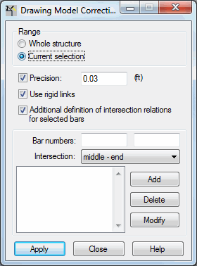
This option improves the geometry of a structure model that was imported from a drawing program so that a correct calculation model of the structure is generated. The correction consists of extending or reducing the length of the members so that the structure members intersect. Open the Drawing Model Correction dialog by clicking Edit menu > Correct Drawing Model.

At the top part of the dialog, the Range field has the following options:
- Whole structure - When selected, the correction is made for the whole structure.
- Current selection - When selected, the correction is made for the selected elements of a structure model.
When Precision is selected; you can enter a distance value (value of the precision parameter) that defines the range in which corrections for a structure drawing model will be made. They corrections are made only when the distance is smaller than precision. When Precision is cleared, the drawing model is automatically corrected by the precision value used by Robot.
When you correct an imported structure model, the original member directions are retained. In most cases, the correction involves extending or reducing the length of a member. However, if there are members which do not lie in one plane, but extend close to each other on 2 different levels, using the Use rigid links option generates rigid links between these members.
When Additional definition of intersection relations for selected members is selected, the options at the bottom of the dialog become available. This option lets you determine whether the selected members should intersect (if yes, then in what way) or not.
To define additional intersection relations of two members:
- Specify (indicate on the screen) in the Member numbers fields, the first and second structure members, for which the intersection relation is to be defined. The order in which you define the members is important.
- Determine the method of intersection:
- End - end
- End - middle
- Middle - end
- Middle - middle
- Without intersection (important when members are located close to each other and an intersection should not be generated.)
- Click Add.
The intersection relation between the indicated members is added to the list of defined relations in the bottom left of the dialog.
Clicking Delete, deletes the member intersection relation from the list; whereas, clicking Modify lets you change the parameters of an intersection relation on the list.
When Apply is clicked, the structure drawing model is corrected.
See also: