Use this option to define the buckling length of members. Access the option by clicking the appropriate icon (for the direction Y or Z) in the Buckling length coefficient field located in the Member Definition - Parameters dialog. The buckling length coefficient is entered automatically. The following dialog displays:
The last icon, which when selected defines additional points where the beam has been protected against flexural buckling. Buckling is considered in calculations when a compressive force, even negligible in relation to other internal forces, is acting on the member. To ignore the buckling effects in calculations, click ![]() . It indicates that buckling is disregarded in the calculation process.
. It indicates that buckling is disregarded in the calculation process.
The last icon enables members with internal bracing (lateral stiffeners of the analyzed members limiting the lateral buckling length) to be included in calculations. After double-clicking the icon, the Internal bracing dialog (where parameters of lateral stiffeners are determined) is displayed .
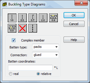
If a complex member is being dealt with, then it is necessary to verify buckling of one or two chords of a two-chord member between the battens.
The settings for Batten type and Connection, will define the calculations for the equivalent slenderness of the analyzed multi-chord column in the X-Y plane (with respect to z axis) .
In the Batten coordinates field the coordinates of battens on a member (this option works as the internal bracing option) are determined. Coordinates may be defined as real or relative (with respect to member length) ones.