Use Analytical Model Categories visibility settings to display Local Coordinate System (LCS) widgets along structural analytical elements in a view.
The widgets are available to linear structural elements. 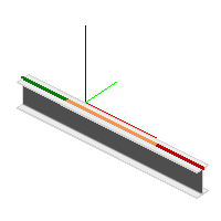
- In the Project Browser, open a plan, elevation, or 3D view.
- Click View tab
 Graphics panel
 (Visibility & Graphics) to open the Visibility/Graphics dialog.
 - Click the Analytical Model Categories tab and expand the structural elements to access and enable the Local Coordinate System widgets. The following elements can display the local coordinate system widgets:
- Analytical Beams
- Analytical Braces
- Analytical Columns
- Analytical Floors
- Analytical Foundation Slabs
- Analytical Walls
Widgets representing the X, Y, and Z axes display along the enabled analytical elements. The Axes are defined as follows
Columns, Braces and Beams
- x (red) longitudinal axis: Orients from the beginning to end analytical model segments of the element.
- y (green) transverse section: The horizontal strong axis.
- z (blue) transverse section: The vertical weak axis.
Walls
- x (red) in-plane axis: Vertical orientation.
- y (green) in-plane axis: Perpendicular to x-axis.
- z (blue) normal axis: Orients from the interior to exterior face.
Floors and Slabs
- x (red) in-plane axis: Orients along the span direction of the element.
- y (green) in-plane axis: Perpendicular to x-axis.
- z (blue) normal axis: Perpendicular to the top surface.