The guidelines for analytical projection are based on the presence of additional elements in relation to the element, the element itself (whether it is a beam, column, floor, or wall), the order of creation, and specified projection properties.
Projection references for linear elements are defined as horizontal and vertical in relation to the local beam coordinate system. Horizontal plane (y-direction) projection references include grids, sides and center of a beam. Vertical plane (z-direction) projection references include levels, top of beam, middle of beam and bottom of beam. Named reference planes are included in the horizontal and vertical projections where appropriate. All sloped planes are included in each projection list. If both projection planes refer to a sloped reference plane the projection point is perpendicular to the sloped plane passing through the location line.
Horizontal Projection
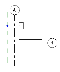
Linear analytical models can project horizontally to a specific reference plane or grid. In the following illustration, the column is projecting to a reference plane parallel to Grid A and the beam is projecting to Grid 1.
| Default analytical meetings | Columns projecting to a reference plane |
|---|---|
 |
 |
For planar elements such as structural floors and foundation slabs, you can project the whole surface to a work plane. The edges of the surface can also be projected to work planes. The projection maintains the planar nature of these elements.
Vertical Projection
- In the vertical direction, structural floors will define the location of the analytical projection planes.
- Top and bottom vertical projection planes for walls will adjust to the analytical projection of a structural floor.
- Top and bottom vertical projection planes for columns will adjust to the analytical projection of a structural floor. Similarly, columns will attempt to project to nearby beams.
Structural floors will always take precedence in the auto-detect behavior.
- Analytical projecting plane of beams will adjust to the analytical projection of a structural floor.
Projection to Elements of the Same Category
- For elements of the same structural category (such as floor-to-floor or wall-to-wall) auto-detect is based on the order of creation, with the highest priority given to the element created first.
- The exception to this rule is when the analytical project parameter has been changed to Projection for one of these elements. Then, that element will have the highest priority. For example, wall 1 is the first wall created, followed by wall 2, then by wall 3, all of which are set to Auto-Detect. If the horizontal projection of wall 2 is changed to center line, then the analytical projection of wall 3 and wall 1 will align to the center line of wall 2.