After you select the stair for editing and select a stair component, modification controls are available for direct manipulation of the component.
 Video: Modify Components in a Stair
To modify stair components
- Select the stair, and click Modify | Stairs tab
 Edit panel
 (Edit Stairs).
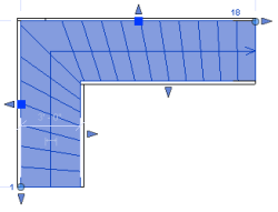
In stair assembly edit mode, riser index numbers display as a reference during editing. These numbers indicate the first and last riser in each run. The numbers update dynamically as changes are made to the stair.
(Edit Stairs).
In stair assembly edit mode, riser index numbers display as a reference during editing. These numbers indicate the first and last riser in each run. The numbers update dynamically as changes are made to the stair.
- Click to select the component to modify. (Press Tab to highlight a component if necessary in order to select it.)
Note: If you select a chain of connected components, such as runs and landings, the direct modification controls are not available.
- Use the direct manipulation controls to modify the stair component. (See the table that follows for descriptions of the numbered direct manipulation controls illustrated below.)
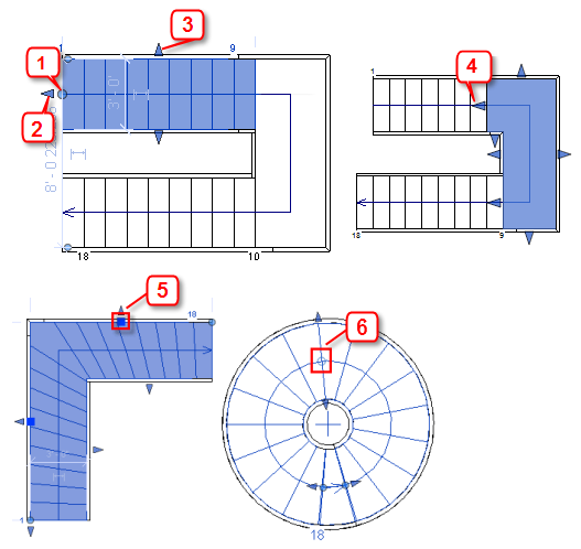
Control Modification Behavior 1 Drag the filled dot control (at the open run end) to reposition the end of the run and to add or remove treads/risers in any direction. (You cannot add treads/risers below the base level of the stair.) 2 Drag the arrow control at the run end along the stair path to add or remove steps. Modifying the run end with the arrow control maintains the stair height. 3 Drag the arrow shape control at one of the run edges to change the width of the run. 4 Drag the arrow control to modify the leg length of the landing where it is connected to a run. You can also use this control on landing edges to resize the landing. 5 Drag the square control on a winder run leg to move the leg. Winder steps are added/removed from the winder legs in the run to maintain the original stair height. 6 Drag the hollow dot control at the middle of a spiral run to change the radius.
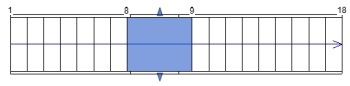
Move a Run
Moving a run repositions the run by a multiple of the riser height value. Connected components, such as an automatic landing, stay joined, and the height of the stair assembly is maintained.
Select the run component, and drag it to the new location. In the following example, the run is moved to the left.

Add/Remove Steps at an Open Run End
You can add or remove treads/risers from an open end of a run. If you add steps to the open end of the top run, they will be above the top elevation of the stair. Notice that the riser index number indicates + and the number of steps added.
Select the run component, and drag the filled dot control to add or remove treads/risers. In the following example, 3 steps were added to the top of the run.

Rotate a Run
Rotate a run by dragging the filled dot control at the end of a run (or by using the Rotate tool on the Modify panel).
Select the run component, and drag the filled dot control (at the open end) to rotate the run. If the run is connected to an automatic landing, the landing shape is adjusted to accommodate the new run angle.

Balance Steps in a Run
You can balance the number of steps in a run, such as a winder run or spiral run, by manipulating one end of the run. The original stair height is maintained, but the configuration of steps changes.
Drag the arrow shape handle at one end of the run to change the configuration of the steps. In this example, the right winder leg is lengthened and the adjacent legs adjust so that the stair height is not changed.
Balance Steps in 2 Runs

- Drag the filled dot control at the end of each run to adjust the number of steps.


- Create a landing by picking the 2 runs or sketch a landing to connect the runs.
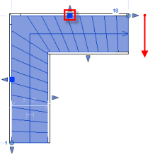
Reposition a Winder Run Leg
You can reposition a leg in a winder run. Other legs in the winder run will remain in the same position, but steps will be added or deleted from the connected winder legs to maintain the original stair height.
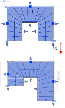
Adjust Headroom Clearance
One way to adjust a stair to meet the headroom clearance requirement is to modify the landing height. Other methods include repositioning a run and balancing the number of treads/risers between runs.
To adjust the landing height, In an elevation view, select the landing, and use the Move tool to change the landing position. (You could also modify the Height instance property for the landing). Notice that the steps adjust between the runs to accommodate the landing height change.

Modify Actual Run Width
You can change the width of a run directly in stair assembly edit mode.
Select the run, and drag the arrow shape control at one of the run edges to change the width. Notice that the width of the connected landing component changes as well.

Reshape a Landing
You can modify the shape of an automatic landing while keeping the runs connected as designed.
Select the landing, and drag the arrow shape controls at the edges to modify the landing size and shape.
