Learn how to manage the visibility and detail level of structural connections in your model.
| Detail Level | Display | Description |
|---|---|---|
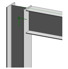
| Medium |  |
Only a symbolic representation of the connection is displayed. |
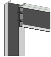
| Fine |  |
The detailed geometry of the connection is displayed. |
- If the connection is not selected, there will be no representation of it.
- If the connection si selected, the connection bounding box and the order/role of the connection input elements will be visible.
The Structural Connection Handler

The connection handler is the representation of the structural steel connection in the model and it marks the join point of the connected elements, the direction of each input element and, if selected, it also shows the order / role of the input elements within the connection.
The handler is displayed differently, depending on the level of detail set in the model:
| Detail Level | Handler Display |
|---|---|
| Coarse |
|
| Medium and Fine |
|
If you select multiple connections, the order /role of the input elements for each selected connection will no longer be displayed.
Use the Structural Connections  Symbol model category in the
Visibility/Graphics Overrides Dialog to set the visibility of structural connections in a specific view.
If the Reference check box is not checked, connections will be selectable but not visible in the view. This allows you to create connection tags in a view without the visible symbols of the connections.