Graphically Display Beam Results
Learn how to display bending moments on beams for a selected load case.
-
Continue working in your project or open the project Frame_3D_Analysis.rtd.
Note: The Tutorial files are located in C:\ProgramData\Autodesk\Examples\Tutorials. -
In the Standard toolbar, expand the Layouts drop-down menu and select Results as shown below:
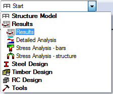
The layout is divided in three parts: View, Diagrams dialog, and Reactions in the coordinate system table.
-
Click in the drawing area to deselect the beam number 6, 7, 11, and 12.
-
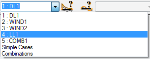
In the Cases Selection box of the Selection toolbar, expand the Cases drop-down menu and select 4: LL1 as shown below:
-
Go to the NTM tab of the Diagrams dialog, select MY Moment, and click Normalize.
Note: Click Normalize to scale the values of the selected type of diagram automatically.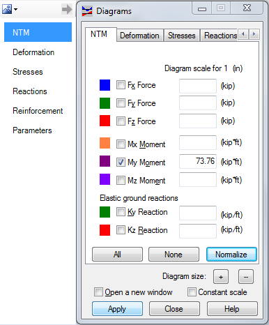
-
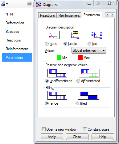
To display numerical values of internal forces, go to the Parameters tab.
Tip: You can access the Parameters tab without having to scroll through the tabs. Place the mouse cursor over the arrow near the top left corner of the dialog to display the list of tabs. -
In the Parameters tab, set the Diagram description to labels, and then select Global extremes from the Values drop-down menu.
-
Click Apply.
-
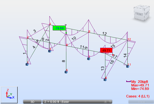
The view displays the bending moment diagrams for all beams as shown below.
-
Go to the NTM tab of the Diagrams dialog, deselect MY Moment, and click Apply.