Quadrilateral Plate Element Connection
Description: Defines a curved quadrilateral isoparametric shell or plane strain element with four to eight grid points.
Format:

Example:

| Field | Definition | Type | Default |
|---|---|---|---|
| EID | Element identification number. | Integer > 0 | Required |
| PID | Identification number of a PSHELL or PCOMP property entry. | Integer > 0 | Required |
| Gi | Grid point identification numbers of connection points. | Integer > 0, all unique | Required |
| Ti | Membrane thickness of element at G1, G2, G3, and G4. | Real ≥ 0.0 or blank | See Remark 9 |
| THETA | Material property orientation angle in degrees. | Real or blank | See Remark 8 |
| MCID | Material coordinate system identification number. | Integer ≥ 0 | See Remark 8 |
| ZOFFS | Offset from the surface of grid points to the element reference plane (see Remark 7). | Real or blank | 0.0 |
Remarks:
- Element identification numbers must be unique with respect to all other element identification numbers.
- Grid points G1 through G8 must be ordered as shown.
- Any or all of the edge points, G5 through G8, may be deleted. If the ID of any edge connection points is left blank or set to zero, the element equations are modified to give the correct results for the reduced number of connections. Corner grid points cannot be deleted.
- It is recommended that the midside grid points be located within the middle third of the edge. If the edge point is located at the quarter point the element may become singular.
- All the interior angles must be less than 180°.
- Stresses are output in the surface coordinate system. (See the SURFACE command in Section 3, Case Control.)
- Elements may be offset from the grid point surface by means of ZOFFS. Other data, such as stress fiber locations are given relative to the reference plane. Positive offset implies that the element reference plane lies above the grid points. Use of a non-zero value for ZOFFS will produce membrane-bending coupling. Users must specify values for MID1, MID2, and MID3 in the PSHELL entry for the element if a non-zero value of ZOFFS is used. ZOFFS values must only be used when membrane and bending action is specified for the element. Absence of either of the actions does not allow development of membrane-bending coupling.
- If THETA/MCID is blank, field 5 of the PSHELL continuation entry will be used. If this field is also blank, then THETA = 0.0 is assumed when a non-isotropic material is referenced.
- If Ti in fields 4 through 7 of the continuation entry are blank, field 4 of the PSHELL entry will be used. This is the preferred way of specifying element thickness if the thickness does not vary over the element.
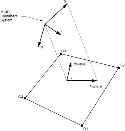
Figure 1. MCID Coordinate System Definition
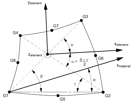
Figure 2. CQUAD8 Element Geometry and Coordinate System
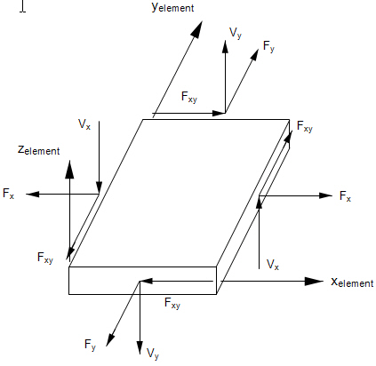
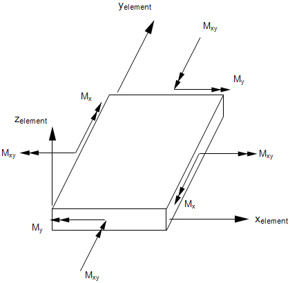
Figure 3. Forces and Moments in CQUAD8 Elements
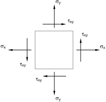
Figure 4. Stresses in CQUAD8 Elements