Click the Displacements tab in the Member Properties dialog to display the following:
The top of the dialog displays a diagram of the quantity selected. The field might display a diagram of only one quantity. The diagrams are redrawn, if the load case changes.
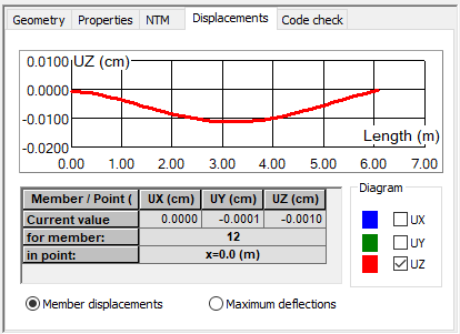
The table displays the following types of displacements:
- Member displacement
- Maximum deflection
When Member displacement is selected, Robot displays the values of global displacements UX, UY, UZ at the point with the indicated coordinate on the member. When you click in the in point field and move the mouse to the diagram at the top, a vertical line displays that lets you define the value of the coordinate for which you want relevant values.
When you click in the for member field and move the mouse to the graphical viewer, then, selecting another member with the mouse updates the contents of the Member properties dialog according to the current selection
When Maximum deflections are selected, the table displays the maximum values of the selected quantity as well as the location of the point for which the maximum value is reached.