The RolledCurb subassembly inserts links for a rolled kerb shape concrete kerb-and-channel with subbase.
Attachment
The attachment point is at the kerb lip or back of kerb. This component can be attached to either the left or right side.
Input Parameters
|
Parameter |
Description |
Type |
Default |
|---|---|---|---|
| Side | Specifies which side to place the subassembly. | Left / Right | Right |
| Top of Kerb | Top of kerb | Numeric, positive |
4.5 in 100 mm |
| Back Height | Back height | Numeric, positive |
14.5 in 370 mm |
| Bottom Width | Bottom width | Numeric, positive |
24 in 600 mm |
| Front Height | Front height | Numeric, positive |
7 in 180 mm |
| Width To Flowline | Width to flowline | Numeric, positive |
11.5 in 300 mm |
| Flowline Height | Flowline height | Numeric, positive |
6.5 in 165 mm |
| Subbase Depth | Subbase depth | Numeric, positive |
12 in 300 mm |
| Attachment Point | Attachment point | Lip, BackKerb | Lip |
Target Parameters
This section lists the parameters in this subassembly that can be mapped to one or more target objects. For more information, see To Specify Corridor Targets.
None.
Runtime Logical Assignments
None.
Output Parameters
None.
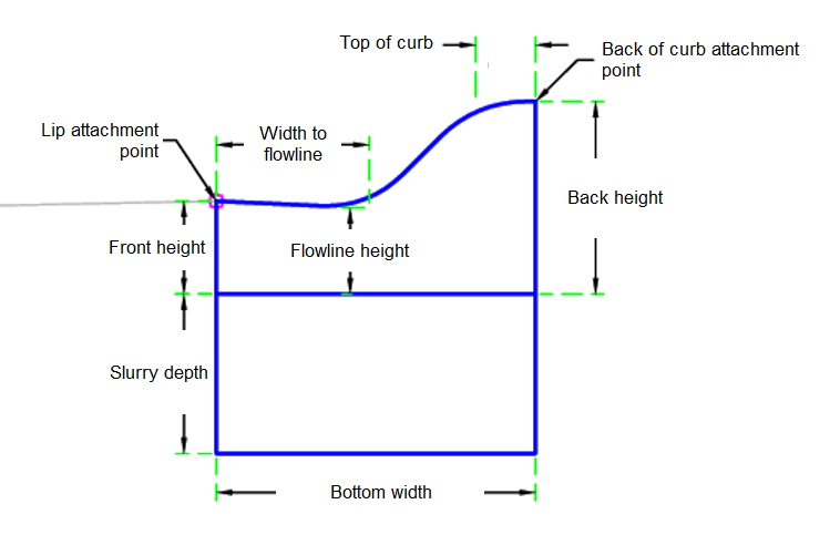
Behavior
The kerb and channel links are inserted based on the Input Parameter dimensions. All dimensions must be positive, non-zero values.
The subassembly builds the shape for a simple kerb and channel, with the attachment point either at (a) lip of the channel, or (b) the back of the kerb.
Layout Mode Operation
In layout mode, this subassembly displays the kerb-and-channel component based on the input parameters given.
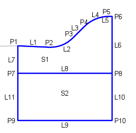
Point, Link and Shape Codes
The following table lists the point, link and shape codes for this subassembly that have codes assigned to them. Point, link or shape codes for this subassembly that do not have codes assigned are not included in this table.
|
Point, Link or Shape |
Code |
Description |
|---|---|---|
| P1 | Flange | |
| P6 | BackOfKerb | |
| P7, P8 | KerbBottom | |
| P9, P10 | SubBase | |
| L1 - L5 | Kerb, Top | |
| L8 | KerbBottom | |
| L9 | Datum | |
| S1 | Kerb | |
| S2 | SubBase |
Coding Diagram