The SLOCityCurbs subassembly inserts links and shapes to create kerbs, channels and footpaths according to the City of San Luis Obispo Standard Plans.
You should verify that the dimensions used match your interpretation of the standard plan.
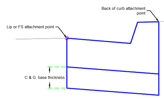
Kerb and Channel:
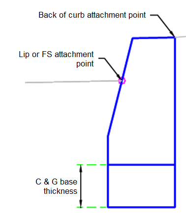
Kerb:
Boardwalk Footpath:
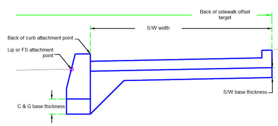
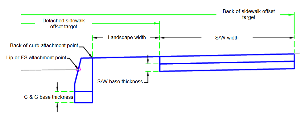
Detached Footpath:
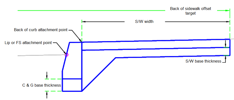
Integral Footpath:
Attachment
The attachment point is at the Lip (or FS) and the Back of Kerb. This component can be attached to either the left or right side.
Input Parameters
|
Parameter |
Description |
Type |
Default |
|---|---|---|---|
| Side | Specifies which side to place the subassembly. | Left / Right | Right |
| Kerb Type | Type of kerb or kerb and channel | Kerb 6" and 24" Channel / Kerb 8" and 24" Channel / Kerb 6" and 18" Channel / Kerb 8" and 18" Channel / Kerb 6" / Kerb 8" | Kerb 6" and 18" Channel |
| Attachment Point | Attachment point for the kerb or kerb and channel | Lip or FS / Back of Kerb | Lip or FS |
| Footpath Type | What type of footpath should be used (or none) | Detached / Integral / Boardwalk / None | None |
| C & G Base Thickness | The thickness of base below the kerb and channel | Numeric, positive |
0.5 ft 0.15 m |
| S/W Base Thickness | The thickness of base under the footpath | Numeric, positive |
0.33 ft 0.10 m |
| S/W Width | The width of the footpath | Numeric |
6 ft 2 m |
| Landscape Width | The width of the landscape when using a detached footpath | Numeric |
3 ft 1 m |
Target Parameters
This section lists the parameters in this subassembly that can be mapped to one or more target objects. For more information, see To Specify Corridor Targets.
|
Parameter |
Description |
Status |
|---|---|---|
| Detached Footpath Offset | May be used to override the fixed footpath width and tie the inside edge of footpath to an offset alignment. The following object types can be used as targets for specifying the width: alignments, polylines, feature lines or survey figures. | Optional |
| Back of Footpath Offset | May be used to override the fixed footpath width and tie the outside edge of footpath to an offset alignment. The following object types can be used as targets for specifying the width: alignments, polylines, feature lines or survey figures. | Optional |
Runtime Logical Assignments
The dimensions of the kerb and channel are stored within the subassembly. At runtime the values are looked up and assigned based on the Kerb Type selected.
Output Parameters
None.
Behavior
The initial point is set at the attachment point. The points, links and shapes of the kerb and channel are built based on the Kerb Type selected. Base is then placed under the kerb and channel.
If the footpath type is not None, then the appropriate footpath and base is built. If the footpath is Detached and the Detached Footpath Offset is set, then the inside footpath edge is adjusted. If the Back of Footpath Offset is set, then the widths of all footpath types are adjusted.
Layout Mode Operation
In layout mode, this subassembly displays the kerb-and-channel and footpath components based on the input parameters given.
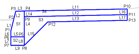
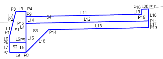
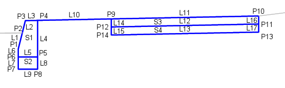
Point, Link and Shape Codes
The following table lists the point, link and shape codes for this subassembly that have codes assigned to them. Point, link or shape codes for this subassembly that do not have codes assigned are not included in this table.
|
Point, Link or Shape |
Code |
Description |
|---|---|---|
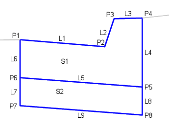
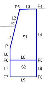
| P1 | Flange | Flange point of the channel |
| P2 | InvertLevel_Channel | Channel invert level point |
| P3 | TopKerb | Top of kerb |
| P4 | BackCurb, Footpath_In | Back of kerb, integral and boardwalk footpath |
| P9 | Footpath_In | Inside edge of footpath on finish surface |
| P10 | Footpath_Out | Outside edge of footpath on finish surface |
| L1 - L3 | Top, Kerb | Finish surface on the kerb and channel |
| L5 | Bottom | Bottom of kerb |
| L9, L13, L18 | Subgrade, Datum | Bottom of base |
| L10 | Top, Sod, Datum | |
| L11, L19 | Top, Footpath | |
| L12 | Footpath_Bottom | Bottom of footpath |
| S1 | Kerb | Kerb-and-channel concrete area |
| S2 | SubBase | |
| S3 | Footpath | Footpath concrete area |
Coding Diagram
Kerb and Channel:
Kerb:
Boardwalk Footpath:
Detached Footpath:
Integral Footpath: