The MultipleBenchWithPipes subassembly creates cut or fill catch slopes with repeating benches as needed.
You can define swale widths at the benches. Pipes are added at each bench. The last daylight slope to the target surface may be different to the bench slope.
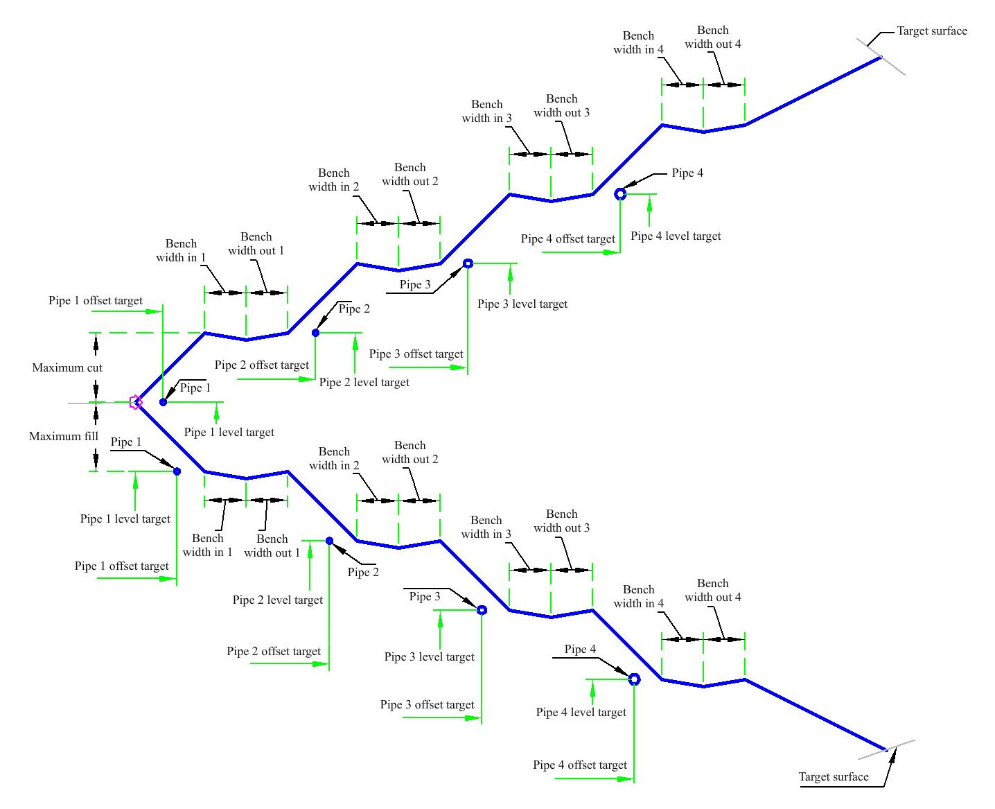
Attachment
The attachment point is at the inside edge of the initial cut or fill slope. This component can be attached to either the left or right side.
Input Parameters
|
Parameter |
Description |
Type |
Default |
|---|---|---|---|
|
Side |
Specifies which side to place the subassembly. |
Left/Right |
Right |
|
Max Cut Depth |
The maximum allowable height for the cut daylight link without benching. |
Numeric, positive |
15 ft 4.5 m |
|
Max Fill Depth |
The maximum allowable height for the fill daylight link without benching. |
Numeric, positive |
10 ft 3.0 m |
|
Daylight Slope Cut |
The slope for the cut daylight slope. |
Numeric, positive |
2 (: 1) |
|
Daylight Slope Fill |
The slope for the fill daylight slope. |
Numeric, positive |
2 (: 1) |
|
Bench Slope 1 |
The slope of bench 1. |
Numeric, positive |
1 (: 1) |
|
Swale Depth 1 |
The depth of the swale at the top of bench 1. |
Numeric, positive |
0.5 ft 0.15 m |
|
Swale Width in 1 |
The width from the front edge of the swale at the top of bench 1 to the invert level. |
Numeric, positive |
5 ft 1.5 m |
|
Swale Width out 1 |
The width from the swale invert level to the bottom of bench 2. |
Numeric, positive |
5 ft 1.5 m |
|
Bench Slope 2 |
The slope of bench 2. |
Numeric, positive |
1 (: 1) |
|
Swale Depth 2 |
The depth of the swale at the top of bench 2. |
Numeric, positive |
0.5 ft 0.15 m |
|
Swale Width in 2 |
The width from the front edge of the swale at the top of bench 2 to the invert level. |
Numeric, positive |
6 ft 2 m |
|
Swale Width out 2 |
The width from the swale invert level to the bottom of bench 3. |
Numeric, positive |
3 ft 1 m |
|
Bench Slope 3 |
The slope of bench 3. |
Numeric, positive |
1 (: 1) |
|
Swale Depth 3 |
The depth of the swale at the top of bench 3. |
Numeric, positive |
0.5 ft 0.15 m |
|
Swale Width in 3 |
The width from the front edge of the swale at the top of bench 3 to the invert level. |
Numeric, positive |
6 ft 2 m |
|
Swale Width out 3 |
The width from the swale invert level to the bottom of bench 4. |
Numeric, positive |
3 ft 1 m |
|
Bench Slope 4 |
The slope of bench 4. |
Numeric, positive |
1 (: 1) |
|
Swale Depth 4 |
The depth of the swale at the top of bench 4. |
Numeric, positive |
0.5 ft 0.15 m |
|
Swale Width in 4 |
The width from the front edge of the swale at the top of bench 4 to the invert level. |
Numeric, positive |
3 ft 1 m |
|
Swale Width out 4 |
The width from the swale invert level to the bottom last daylight link. |
Numeric, positive |
3 ft 1 m |
|
Pipe1 Size |
Diameter of Pipe 1. |
Numeric, positive |
4 inches 0.1 m |
|
Pipe1 Offset |
Offset of Pipe 1 from the edge of Bench 1. |
Numeric, positive |
5 ft 1.5 m |
|
Pipe2 Size |
Diameter of Pipe 2. |
Numeric, positive |
4 inches 0.1 m |
|
Pipe2 Offset |
Offset of Pipe 2 from the edge of Bench 2. |
Numeric, positive |
5 ft 1.5 m |
|
Pipe3 Size |
Diameter of Pipe 3. |
Numeric, positive |
6 inches 0.15 m |
|
Pipe3 Offset |
Offset of Pipe 3 from the edge of Bench 3. |
Numeric, positive |
5 ft 1.5 m |
|
Pipe4 Size |
Diameter of Pipe 4. |
Numeric, positive |
8 inches 0.2 m |
|
Pipe4 Offset |
Offset of Pipe 4 from the edge of Bench 4. |
Numeric, positive |
5 ft 1.5 m |
Target Parameters
This section lists the parameters in this subassembly that can be mapped to one or more target objects. For more information, see To Specify Corridor Targets.
|
Parameter |
Description |
Status |
|---|---|---|
| Daylight Surface | Name of the daylighting surface. The following object types can be used as targets for specifying the surface: surfaces. | Required |
| Pipe1 Offset | May be used to override the Pipe1 Offset and tie Pipe1 to an offset alignment. The following object types can be used as targets for specifying the offset: alignments, polylines, feature lines, or survey figures. | Optional |
| Pipe1 Level | May be used to override the Pipe1 Level. The following object types can be used as targets for specifying this level: profiles, 3D polylines, feature lines, or survey figures. | Optional |
| Pipe2 Offset | May be used to override the Pipe2 Offset and tie Pipe2 to an offset alignment. The following object types can be used as targets for specifying the offset: alignments, polylines, feature lines, or survey figures. | Optional |
| Pipe2 Level | May be used to override the Pipe2 Level. The following object types can be used as targets for specifying this level: profiles, 3D polylines, feature lines, or survey figures. | Optional |
| Pipe3 Offset | May be used to override the Pipe3 Offset and tie Pipe3 to an offset alignment. The following object types can be used as targets for specifying the offset: alignments, polylines, feature lines, or survey figures. | Optional |
| Pipe3 Level | May be used to override the Pipe3 Level. The following object types can be used as targets for specifying this level: profiles, 3D polylines, feature lines, or survey figures. | Optional |
| Pipe4 Offset | May be used to override the Pipe4 Offset and tie Pipe4 to an offset alignment. The following object types can be used as targets for specifying the offset: alignments, polylines, feature lines, or survey figures. | Optional |
| Pipe4 Level | May be used to override the Pipe4 Level. The following object types can be used as targets for specifying this level: profiles, 3D polylines, feature lines, or survey figures. | Optional |
Runtime Logical Assignments
None.
Output Parameters
None.
Behavior
The initial hinge point is set at the attachment point. The hinge point level is checked against the target surface to determine if the section is in the cut or fill condition. An intercept is calculated to the target surface using the given Daylight Slope. If the height to the intercept exceeds the Max Daylight Height, the link with the Bench Height is inserted and the bench is added. The hinge point is reset to the outside edge of the bench and the process is repeated until a daylight link is found that does not exceed the Max Daylight Height. Each bench, up to four, uses the input parameters for each bench depth and width.
At each bench a pipe is inserted at a distance specified in the input parameters or overridden using targets for offset and level. A pipe size of 0 omits the pipe.
Layout Mode Operation
In layout mode, this subassembly draws the initial fill slope to 5 units.
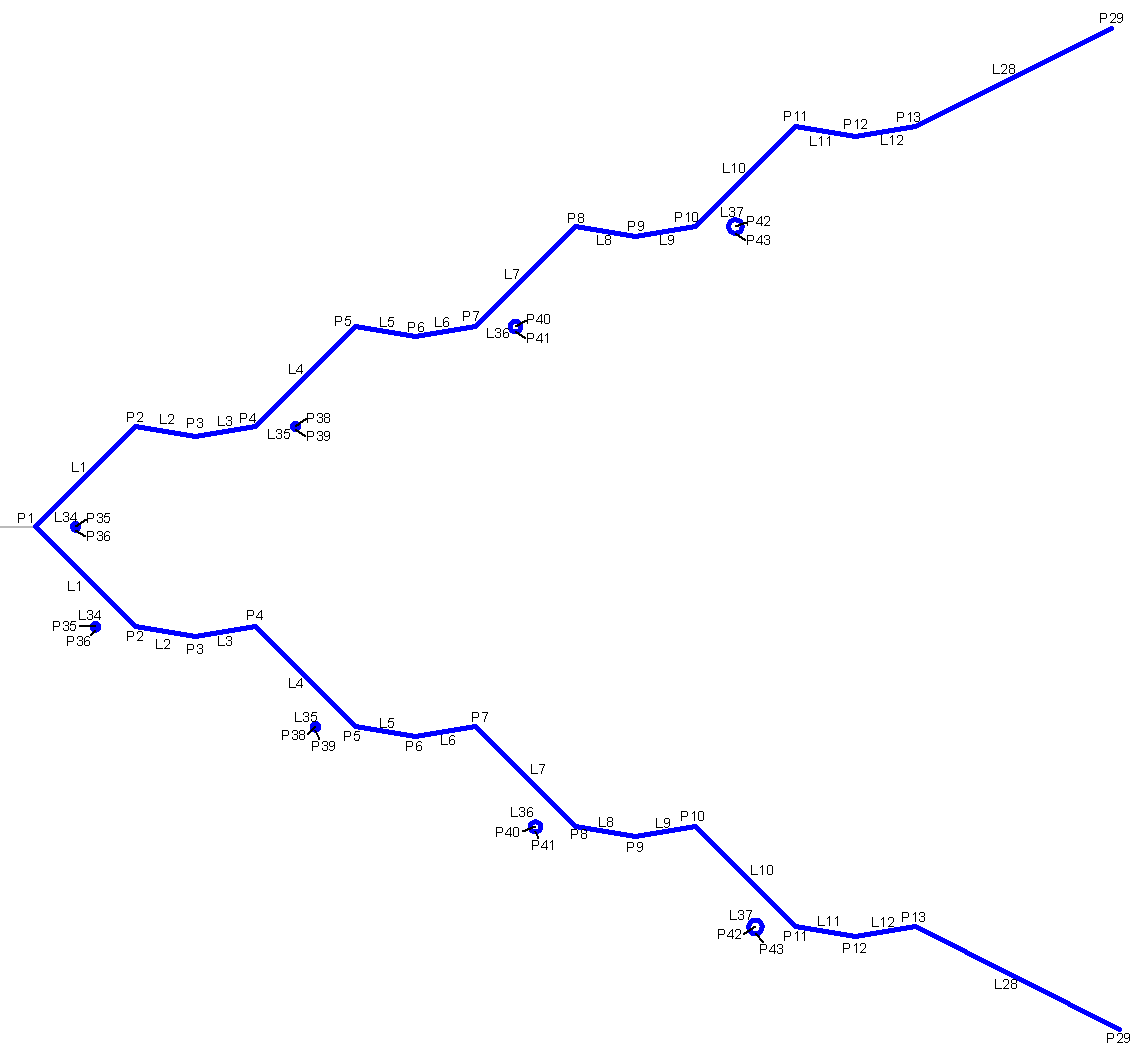
Point, Link and Shape Codes
The following table lists the point, link and shape codes for this subassembly that have codes assigned to them. Point, link, or shape codes for this subassembly that do not have codes assigned are not included in this table.
|
Point, Link, or Shape |
Code |
Description |
|---|---|---|
| P1 | Hinge | |
| P2, P5, P8, P11 | Bench_In | |
| P3, P6, P9, P12 | Ditch | |
| P4, P7, P10, P13 | Bench_Out | |
| P25 - P29 | Daylight | |
| P35, P38, P40, P42 | PipeCentre | |
| P36, P39, P41, P43 | Pipe_Invert | |
| L1, L4, L7, L10 | Top, Datum, Bench | |
| L2, L3, L5, L6, L8, L9, L11, L12 | Top, Datum, Swale | |
| L24, L26, L27, L28 | Top, Datum, Daylight | |
| L34, L35, L36, L37 | Pipe |
Coding Diagram