The ClarkCountyKerbE1 subassembly inserts links to create a kerb at the specified insertion point. The shape represents the Clark County Kerb, Type E1.
You should verify that the dimensions used match your interpretation of the standard plan.
Attachment
The attachment point is at the inside edge of the initial cut or fill slope. This component can be attached to either the left or right side.
Input Parameters
|
Parameter |
Description |
Type |
Default |
|---|---|---|---|
| Side | Specifies which side to place the subassembly. | Left / Right | Right |
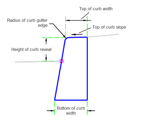
| Bottom of Kerb Width | Bottom of Kerb Width | Numeric, positive |
8.25 in 0.21 m |
| Top of Kerb Width | Top of Kerb Width | Numeric, positive |
5.5 in 0.14 m |
| Radius of Kerb Channel Edge | Radius of Kerb Channel Edge | Numeric, positive |
1 in 0.025 m |
| Total Height of Kerb | Total Height of Kerb | Numeric, positive |
16 in 0.40m |
| Height of Kerb Reveal | Height of Kerb Reveal | Numeric, positive |
6 in 0.15 m |
| Top of Kerb Slope | Top of Kerb Slope | Numeric, positive | 50 ( : 1) |
| Attachment Point | Kerb attachment point | Flowline / Back | Flowline |
Target Parameters
This section lists the parameters in this subassembly that can be mapped to one or more target objects. For more information, see To Specify Corridor Targets.
None.
Runtime Logical Assignments
None.
Output Parameters
None.
Behavior
The subassembly builds a Clark County Kerb, Type E1, shape for a kerb, with the attachment point at the flowline or the back of kerb.
Layout Mode Operation
In layout mode, this subassembly draws the kerb shape as specified by the input parameters.
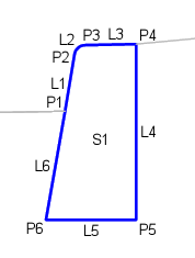
Point, Link and Shape Codes
The following table lists the point, link and shape codes for this subassembly that have codes assigned to them. Point, link or shape codes for this subassembly that do not have codes assigned are not included in this table.
|
Point, Link or Shape |
Code |
Description |
|---|---|---|
| P1 | InvertLevel_Channel | Flowline of the kerb |
| P3 | Top_Kerb | Top of the kerb |
| P4 | Back_Kerb | Back of the kerb |
| L1 - L3 | Top, Kerb | Top of the kerb |
| L4 - L6 | Datum, Kerb | Datum of the kerb |
| S1 | Kerb | Concrete shape of the kerb |
Coding Diagram