The Benching subassembly inserts links to create a benching. The benching may be created from the inside toe or inside top of the benching. The benching then daylights to a surface.
Attachment
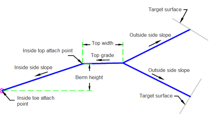
The attachment point is at the inside toe or inside top of the benching. This component can be attached to either the left or right side.
Input Parameters
|
Parameter |
Description |
Type |
Default |
|---|---|---|---|
| Side | Specifies which side to place the subassembly. | Left / Right | Right |
| Attach Point | Attach point where the benching will be built from. | Inside Toe / Inside Top | Inside Toe |
| Benching Height | Height of benching measured from the attachment point. | Numeric |
4 ft 1.2 m |
| Outside Side Slope | Benching slope on the outside of the benching. | Numeric | -2 ( : 1) |
| Inside Side Slope | Benching slope on the inside of the benching. | Numeric | 3 ( : 1) |
| Top Gradient | Gradient of the top of the benching. | Numeric | 2 (%) |
| Top Width | Top width of the benching. | Numeric, positive |
5 ft 1.5 m |
Target Parameters
This section lists the parameters in this subassembly that can be mapped to one or more target objects. For more information, see To Specify Corridor Targets.
|
Parameter |
Description |
Status |
|---|---|---|
| Benching Surface | Name of the daylighting surface. The following object types can be used as targets for specifying the surface: surfaces. | Optional |
Runtime Logical Assignments
None.
Output Parameters
None.
Behavior
The initial inside link of the benching is created using the entered height and inside side slope. The top of the benching is created using the entered Top Width and Top Gradient. A daylight link is found using the Outside Side Slope.
Layout Mode Operation
In layout mode, this subassembly draws the benching in fill with a link of 5 ft (1.5 m).
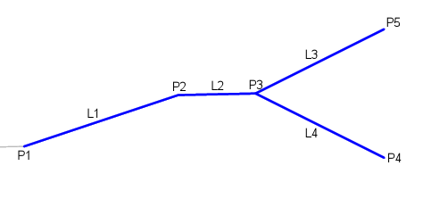
Point, Link and Shape Codes
The following table lists the point, link and shape codes for this subassembly that have codes assigned to them. Point, link or shape codes for this subassembly that do not have codes assigned are not included in this table.
|
Point, Link or Shape |
Code |
Description |
|---|---|---|
| P1 | Benching_Bottom | Bottom inside toe of the benching |
| P2 | Benching_Top_Inside, | Top inside of the benching |
| P3 | Benching_Top_Outside | Outside top of the benching |
| P4 | Daylight, Daylight_Cut | Cut slope stake point |
| P5 | Daylight, Daylight_Fill | Fill slope stake point |
| L1 - L4 | Benching,Top,Datum | Benching top and datum |
| L3 | Daylight_Fill, Daylight | Daylight link for fill section |
| L3 | Daylight_Cut, Daylight | Daylight link for cut section |
Coding Diagram