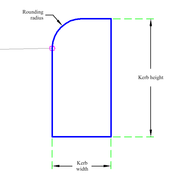
The KerbWallRadius subassembly is used as a standard 6" (0.15 m) / 12" (0.30 m) kerb wall with user defined input for multiple widths and for the kerb radius.
Attachment
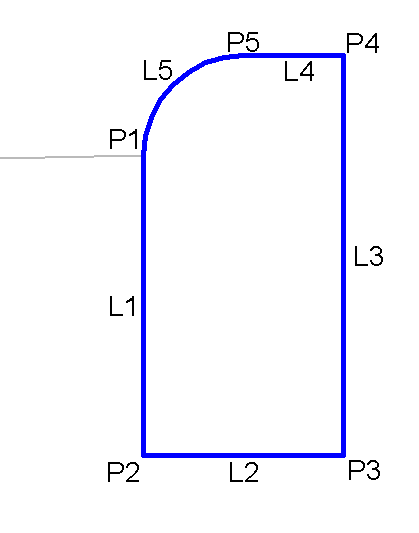
The attachment point is at the start of the kerb wall radius point.
Input Parameters
|
Parameter |
Description |
Type |
Default |
|---|---|---|---|
|
Side |
Specifies which side to place the subassembly. | Left/Right |
Right |
|
Kerb Width |
Width of kerb. | Numeric, positive |
0.5 ft 0.15 m |
|
Kerb Height |
Height of kerb. | Numeric, positive |
1 ft 0.30 m |
|
Rounding Radius |
Radius for the rounding at the front of the kerb. | Numeric, positive |
0.5 ft 0.15 m |
Target Parameters
None.
Runtime Logical Assignments
None.
Output Parameters
|
Parameter |
Description |
Status |
|---|---|---|
|
Used Radius |
Solved radius of the kerb. | Numeric, positive |
Behavior
The kerb links are inserted based on the Input Parameter dimensions. All dimensions must be positive, non-zero values to get the best results. The parameters are checked to ensure if the input radius will give a valid result.
In order to provide a mathematically possible solution, the subassembly will compare the radius to both the width and height entered. If the width or height is smaller than the radius then one-half of the smaller value of width or height will be used.
The subassembly builds the shape for a simple kerb with radius, with the attachment point at the bottom radius of the kerb.
Layout Mode Operation
In layout mode, this subassembly displays the kerb component based on the input parameters given.
Point, Link, and Shape Codes
The following table lists the point, link and shape codes for this subassembly that have codes assigned to them. Point, link or shape codes for this subassembly that do not have codes assigned are not included in this table.
|
Point, Link or Shape |
Code |
Description |
|---|---|---|
| P1 | Attachment | Kerb attachment point |
| P2 | Face_Kerb, Datum | Face of kerb |
| P3 | Datum | |
| P4 | Back_Kerb | Back of kerb |
| P5 | Top | |
| L1 | Kerb, Datum | Kerb below attachment point |
| L2 | Datum | |
| L3 | KerbBack | Back of kerb |
| L4 - L5 | Top | |
| S1 | Kerb |
Coding Diagram