The ClarkCountyExtrudedCurb subassembly inserts links to create a Clark County Extruded Kerb.
You should verify that the dimensions used match your interpretation of the standard plan.
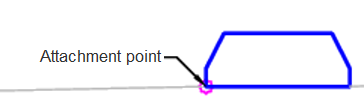
Case 1: Type 1
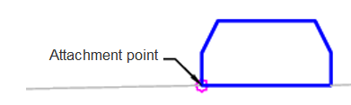
Case 1: Type 2
Case 1: Type 3
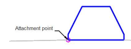
Attachment
The attachment point is on the front edge of the kerb.
Input Parameters
|
Parameter |
Description |
Type |
Default |
|---|---|---|---|
| Side | Specifies which side to place the subassembly. | Left / Right | Right |
| Kerb Type | Kerb type to use | Type 1 / Type 2 / Type 3 | Type 3 |
Target Parameters
This section lists the parameters in this subassembly that can be mapped to one or more target objects. For more information, see To Specify Corridor Targets.
Runtime Logical Assignments
None.
Output Parameters
None.
Behavior
The subassembly builds a Clark County Extruded Kerb based on the type selected.
Layout Mode Operation
In layout mode, this subassembly draws the kerb shape as specified by the input parameters.
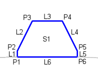
Point, Link and Shape Codes
The following table lists the point, link and shape codes for this subassembly that have codes assigned to them. Point, link or shape codes for this subassembly that do not have codes assigned are not included in this table.
|
Point, Link or Shape |
Code |
Description |
|---|---|---|
| P3 | ExtrCRB_Top_In | Top inside of the extruded kerb |
| P4 | ExtrCRB_Top_Out | Top outside of the extruded kerb |
| L1 - L5 | ExtrCurb | Extruded kerb |
| L6 | ExtrCurb, Datum | Bottom of extruded kerb |
| S1 | Extr_Curb | Extruded kerb concrete |
Coding Diagram